14. Timers in PLC Programming: TON, TOF, and RTO ( 14 of 35 )
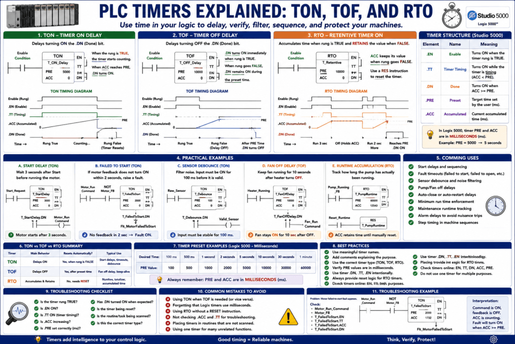
Timers are one of the most common instructions used in PLC programming.
A timer allows the PLC to use time as part of the control logic.
In simple words:
A PLC timer waits for a programmed amount of time before changing a status bit.Timers are used when a machine needs to delay, verify, filter, or sequence an action.
Common industrial uses:
Motor start delay
Conveyor delay
Valve open timeout
Sensor debounce
Alarm delay
Auto-close timer
Pump minimum run time
Failed-to-start fault
Flashing light logic
Sequence step delay
In Studio 5000 / Logix controllers, timers are structured tags with elements such as .EN, .TT, .DN, .PRE, and .ACC. The Studio 5000 lab material also notes that Logix timer presets are DINT values and are entered in milliseconds.
Why Timers Matter in Real Machines
Machines do not always react instantly.
Sometimes we need to:
Wait before starting something.
Wait before stopping something.
Confirm a signal is stable.
Detect when something took too long.
Hold an output ON for a minimum time.
Delay an alarm so it does not nuisance trip.
Example:
Command motor ON.
Wait 2 seconds.
If motor feedback is still OFF, generate fault.
That is a timer-based fault.
Another example:
Photoeye turns ON.
Wait 100 ms.
If still ON, accept the signal as valid.
That is debounce logic.
Timers make PLC logic more stable and more realistic.
Main PLC Timer Types
The three timer types most technicians should understand first are:
TON = Timer On Delay
TOF = Timer Off Delay
RTO = Retentive Timer On
Simple memory rule:
TON = delays turning ON
TOF = delays turning OFF
RTO = remembers accumulated time
Timer Structure in Studio 5000
A timer is not just one bit.
A timer is a data structure with multiple elements.
Common timer elements:
| Timer Element | Meaning |
|---|---|
.EN | Enable bit |
.TT | Timer Timing bit |
.DN | Done bit |
.PRE | Preset time |
.ACC | Accumulated time |
Example timer tag:
T_MotorStartDelayTimer elements:
T_MotorStartDelay.EN
T_MotorStartDelay.TT
T_MotorStartDelay.DN
T_MotorStartDelay.PRE
T_MotorStartDelay.ACC
Timer Elements Explained
.PRE — Preset
The preset is the target time.
Example:
T_StartDelay.PRE = 5000In Logix 5000, this means:
5000 ms = 5 seconds.ACC — Accumulated Time
The accumulated value is the time that has already counted.
Example:
T_StartDelay.ACC = 2300This means:
The timer has accumulated 2.3 seconds..EN — Enable Bit
The enable bit turns ON when the timer rung is true.
Example:
Timer rung true → .EN = 1
Timer rung false → .EN = 0
.TT — Timer Timing Bit
The timing bit is ON while the timer is actively timing.
Usually:
Rung true
AND ACC < PRE
THEN .TT = 1
When the timer reaches the preset, .TT turns OFF.
.DN — Done Bit
The done bit turns ON when the timer reaches the preset.
Example:
ACC >= PRE → .DN = 1This is the bit most commonly used in logic.
1. TON — Timer On Delay
What Is a TON Timer?
A TON timer delays turning ON its done bit.
Simple rule:
TON waits while the rung is true.
When ACC reaches PRE, DN turns ON.
Example:
Input turns ON.
Timer starts counting.
After 5 seconds, timer DN bit turns ON.
TON Behavior
| Condition | Timer Result |
|---|---|
| Rung false | Timer reset, ACC = 0, DN = 0 |
| Rung true | Timer starts accumulating |
| ACC < PRE | TT = 1, DN = 0 |
| ACC >= PRE | TT = 0, DN = 1 |
TON Example: Start Delay
Requirement
After the operator presses Start, wait 3 seconds before starting the motor.
Tags
Start_Request
T_StartDelay
T_StartDelay.DN
Motor_Run_Command
Logic Concept
Start_Request → TON T_StartDelay 3000 ms
T_StartDelay.DN → Motor_Run_Command
Plain English
If Start_Request is ON for 3 seconds,
turn ON Motor_Run_Command.
This is useful when you need a controlled delay before starting a motor, pump, or conveyor.
TON Example: Failed-To-Start Fault
This is one of the best industrial uses for a TON timer.
Requirement
If the PLC commands the motor to run, but feedback does not turn ON within 2 seconds, generate a fault.
Logic Concept
Motor_Run_Command AND NOT Motor_Running_Feedback
→ TON T_FailedToStart 2000 ms
When timer is done:
T_FailedToStart.DN → Flt_Motor_FailedToStartPlain English
If the motor is commanded ON
and the motor feedback does not prove running
for 2 seconds,
latch a failed-to-start fault.
This helps troubleshoot:
Bad starter coil
Blown fuse
Overload trip
VFD fault
Loose wire
Failed output
Bad auxiliary contact
2. TOF — Timer Off Delay
What Is a TOF Timer?
A TOF timer delays turning OFF its done bit.
Simple rule:
TOF keeps DN ON for a period of time after the rung goes false.Example:
Input turns ON → DN turns ON immediately.
Input turns OFF → timer starts timing.
After preset time, DN turns OFF.
TOF Behavior
| Condition | Timer Result |
|---|---|
| Rung true | DN = 1, ACC = 0 |
| Rung goes false | Timer starts timing |
| ACC < PRE | DN remains 1 |
| ACC >= PRE | DN turns OFF |
TOF Example: Fan Off Delay
Requirement
When a heater turns OFF, keep the cooling fan running for 10 seconds.
Logic Concept
Heater_Running → TOF T_FanOffDelay 10000 ms
T_FanOffDelay.DN → Fan_Run_Command
Plain English
Fan turns ON while heater is running.
When heater stops, fan remains ON for 10 seconds.
Then fan turns OFF.
This is a common off-delay application.
TOF Example: Keep Conveyor Running After Sensor Clears
Requirement
When a photoeye no longer detects a box, keep the conveyor running for 1 second to clear the product.
Logic Concept
Box_Present_PE → TOF T_ClearDelay 1000 ms
T_ClearDelay.DN → Conveyor_Run_Command
This prevents the conveyor from stopping immediately when the sensor clears.
3. RTO — Retentive Timer On
What Is an RTO Timer?
An RTO timer is a retentive timer.
Simple rule:
RTO accumulates time while the rung is true and keeps its ACC value when the rung goes false.Unlike a TON, an RTO does not reset automatically when the rung goes false.
You must reset it with a reset instruction.
RTO Behavior
| Condition | Timer Result |
|---|---|
| Rung true | ACC accumulates |
| Rung false | ACC is retained |
| ACC >= PRE | DN turns ON |
| Reset instruction active | ACC resets to 0, DN resets |
The PLC reference material explains that retentive instructions keep their value after the ladder condition is de-energized; this idea applies to latch instructions and also appears again when discussing timers.
RTO Example: Machine Runtime
Requirement
Track how long a pump has actually been running.
Logic Concept
Pump_Running_Feedback → RTO T_PumpRuntimeWhen the pump stops:
T_PumpRuntime.ACC stays stored.When maintenance resets the runtime:
Reset_PumpRuntime → RES T_PumpRuntimeThis is useful for:
Runtime tracking
Maintenance intervals
Filter change reminders
Pump service hours
Motor operating time
RTO Example: Accumulated Fault Time
Requirement
Track how long a machine has been in fault during a shift.
Fault_Active → RTO T_FaultTime
Shift_Reset → RES T_FaultTime
This can help with downtime tracking.
TON vs TOF vs RTO Comparison
| Timer | Main Behavior | Resets Automatically? | Common Use |
|---|---|---|---|
| TON | Delays ON | Yes, when rung false | Start delay, fault timeout, debounce |
| TOF | Delays OFF | Yes, after timing | Fan off delay, keep-alive delay |
| RTO | Accumulates and remembers time | No, needs reset | Runtime, maintenance hours, accumulated time |
Timer Timing Diagram Concept
TON
Input:  OFF ─── ON ───────────── OFF
ACC:          0 → PRE
DN:    OFF ─────── after delay ON ─ OFF
TOF
Input:  OFF ─── ON ───── OFF
DN:          ON immediately ─ stays ON during delay ─ OFF
RTO
Input:  ON for 3 sec → OFF → ON for 2 sec
ACC:    3 sec retained + 2 sec = 5 sec
DN:     ON when total reaches PRE
Timers and the PLC Scan
Timers depend on the PLC scan cycle.
The timer instruction must be scanned by the PLC for it to update.
If a routine is not being scanned, the timer may not update.
Also remember:
Timers do not stop real time.
Timers create logic delays based on PLC execution.
The PLC scan cycle and program execution affect how timer instructions are evaluated. Timer logic should be placed where it is scanned consistently.
Timer Presets in Studio 5000
In Studio 5000, timer presets are normally entered in milliseconds.
Examples:
| Desired Time | Preset Value |
|---|---|
| 100 ms | 100 |
| 500 ms | 500 |
| 1 second | 1000 |
| 2 seconds | 2000 |
| 5 seconds | 5000 |
| 30 seconds | 30000 |
| 1 minute | 60000 |
Example:
T_Debounce.PRE = 100Means:
100 ms debounceExample:
T_AutoClose.PRE = 10000Means:
10 second auto-close delayTimers in RSLogix 500
In RSLogix 500 / SLC 500 systems, timer addressing may look like:
T4:0
T4:1
T4:2
Timer elements may look like:
T4:0/DN
T4:0/TT
T4:0/EN
T4:0.PRE
T4:0.ACC
In Studio 5000, the same idea uses tag structure:
T_StartDelay.DN
T_StartDelay.TT
T_StartDelay.EN
T_StartDelay.PRE
T_StartDelay.ACC
Same concept, different platform style.
Practical Timer Applications
1. Sensor Debounce
Problem:
Sensor signal chatters ON/OFF quickly.Solution:
Raw_Input must stay ON for 100 ms before Valid_Input turns ON.Timer:
TON T_InputOnDebounce 100 msUse:
T_InputOnDebounce.DN → Valid_Input2. Fault Timeout
Problem:
Command is ON, but feedback does not happen.Solution:
Start a TON when command is ON and feedback is OFF.Example:
Valve_Open_Command AND NOT Valve_Open_FB
→ TON T_ValveOpenTimeout 5000 ms
If done:
Flt_ValveFailedToOpen = 13. Auto-Close Delay
Problem:
Door should close automatically after staying open for 10 seconds.Solution:
Door_Fully_Open AND AutoClose_Enable
→ TON T_AutoClose 10000 ms
If done:
AutoClose_Request = 14. Alarm Delay
Problem:
Pressure momentarily drops for 200 ms, but this should not create an alarm.Solution:
Pressure_Low → TON T_LowPressureAlarmDelay 2000 msIf pressure remains low for 2 seconds:
Alarm_LowPressure = 15. Minimum Run Time
Problem:
Pump should not short-cycle.Solution:
Once pump starts, keep it running for minimum time unless safety/fault stops it.This may use timers plus start/stop permissive logic.
Timer Done Bit vs Timer Timing Bit
Many beginners use only .DN, but .TT is also useful.
Use .DN when:
You want to act after the timer finishes.Example:
T_StartDelay.DN → Start motorUse .TT when:
You want something active while the timer is timing.Example:
T_StartDelay.TT → Flash “Starting…” lightUse .EN when:
You want to know the timer instruction is enabled.Example:
T_FaultDelay.EN → Show “Fault delay active”Common Beginner Mistakes
Mistake 1 — Forgetting Studio 5000 Uses Milliseconds
Wrong expectation:
PRE = 5Thinking it means 5 seconds.
In Logix, that usually means:
5 msCorrect for 5 seconds:
PRE = 5000Mistake 2 — Using TON When TOF Is Needed
If you need a device to remain ON after the condition turns OFF, use TOF.
Example:
Fan should stay ON after heater stops.This is usually TOF behavior, not TON behavior.
Mistake 3 — Using RTO Without Reset
RTO retains accumulated time.
If you never reset it, it may stay done forever.
Always include a reset condition:
Reset_Runtime → RES T_RuntimeMistake 4 — Using Timer DN as a Command Without Understanding Reset
If the TON rung goes false, .DN resets.
That may turn off logic unexpectedly.
Always check what controls the timer rung.
Mistake 5 — Timer Not Being Scanned
If a timer is inside a routine that is not called, it will not update.
Check:
Is the routine being scanned?
Is the JSR active?
Is the task running?
Is the logic skipped by JMP/MCR?
Automation Technician Notes
When troubleshooting timers, ask:
Is the timer rung true?
Is .EN ON?
Is .TT ON?
Is .ACC increasing?
Is .PRE correct?
Has .DN turned ON?
Is the timer being reset?
Is the routine being scanned?
Is the preset in milliseconds or seconds?
Is this supposed to be TON, TOF, or RTO?
A timer problem is often not the timer itself.
It is usually the logic enabling, resetting, or using the timer.
Practical Troubleshooting Example
Problem
A motor failed-to-start fault appears immediately.
Timer Logic
Motor_Run_Command AND NOT Motor_Running_Feedback
→ TON T_FailedToStart
Possible Causes
Preset is too low
Feedback tag is wrong
Feedback input is not mapped
Motor feedback is normally closed but programmed incorrectly
Timer ACC was not reset
Command is turning ON before output hardware is ready
Best Checks
Check .PRE value.
Check .ACC.
Check .DN.
Check Motor_Run_Command.
Check Motor_Running_Feedback.
Check physical feedback input.
Check if the timer rung is true before expected.
Practical Troubleshooting Example 2
Problem
A debounce input is too slow.
Possible Cause
Debounce preset is too high.Example:
T_Debounce.PRE = 2000That means the input must stay ON for 2 seconds.
For a photoeye, that may be too long.
Better value may be:
50 ms to 200 msdepending on the application.
Best Practices for PLC Timers
Use these habits:
Use descriptive timer names.
Use comments explaining the timer purpose.
Use milliseconds clearly in descriptions.
Use TON for ON delays.
Use TOF for OFF delays.
Use RTO only when accumulated time must be retained.
Always provide reset logic for RTO.
Avoid using one timer for multiple unrelated purposes.
Check command and feedback with timers for diagnostics.
Use timer bits intentionally: EN, TT, DN.
Examples of good timer names:
T_MotorStartDelay
T_ValveOpenTimeout
T_PhotoeyeDebounce
T_AutoCloseDelay
T_FanOffDelay
T_PumpRuntime
Key Terms
| Term | Meaning |
|---|---|
| Timer | PLC instruction that uses time in logic |
| TON | Timer On Delay |
| TOF | Timer Off Delay |
| RTO | Retentive Timer On |
.EN | Timer enable bit |
.TT | Timer timing bit |
.DN | Timer done bit |
.PRE | Preset time |
.ACC | Accumulated time |
| Retentive | Keeps accumulated value when rung goes false |
| Non-Retentive | Resets when rung goes false |
| RES | Reset instruction |
| Debounce | Filtering short unstable signal changes |
| Timeout | Fault generated when expected feedback does not occur in time |
Final Thoughts
Timers are one of the most useful tools in PLC programming.
A TON delays an action from turning ON.
A TOF delays an action from turning OFF.
An RTO accumulates time and remembers it until reset.
For an Automation Technician, timers are essential for troubleshooting because they are often used in fault delays, debounce logic, start delays, auto-close functions, valve timeouts, and runtime tracking.
The key lesson is:
Do not only look at the timer DN bit.
Check EN, TT, ACC, PRE, reset logic, and the rung conditions.
Once you understand timers, many PLC programs become much easier to read and diagnose.