26. Input Malfunctions: How to Troubleshoot PLC Inputs ( 26 of 35 )
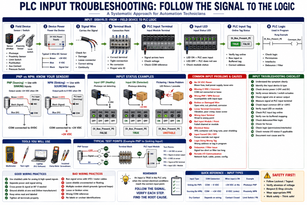
PLC input problems are very common in industrial automation.
A machine may stop, refuse to start, stay stuck in a sequence, or show an HMI alarm because the PLC is not seeing an input correctly.
Common input devices include:
Pushbuttons
Selector switches
Limit switches
Photoeyes
Proximity sensors
Pressure switches
Level switches
Motor overload auxiliary contacts
VFD running contacts
Valve feedback switches
Safety relay feedback contacts
A PLC input is the way the controller knows what is happening in the real machine.
If the PLC does not receive the correct input signal, the logic may never allow the next action.
The source material explains that PLC input interfaces convert signals from field devices such as switches, sensors, and relay contacts into digital data for the processor. It also explains that discrete input channels often use optocouplers to isolate PLC electronics from field voltage and electrical spikes.
The Basic Rule
When troubleshooting a PLC input, follow the signal path.
Field Device
    ↓
Device Power
    ↓
Signal Wire
    ↓
Terminal Block
    ↓
PLC Input Terminal
    ↓
Input LED
    ↓
PLC Input Tag
    ↓
PLC Logic
The goal is to find where the signal stops.
Do not assume the sensor is bad.
Do not assume the PLC input card is bad.
Prove each point step by step.
What Is a PLC Input Malfunction?
A PLC input malfunction happens when the PLC input status does not match the real field condition.
Examples:
Sensor detects product, but PLC input stays OFF.
Limit switch is made, but input LED does not turn ON.
PLC input LED is ON, but the PLC tag does not change.
Input flickers randomly.
Input stays ON all the time.
Input works sometimes but fails intermittently.
Input is inverted in the logic.
Replacement sensor LED turns ON, but PLC does not see it.
Input malfunctions can be caused by electrical, mechanical, wiring, configuration, or logic problems.
Common Causes of PLC Input Problems
Input problems may come from:
No 24 VDC power
Missing 0 VDC/common
Blown fuse
Bad sensor
Misaligned photoeye
Damaged cable
Loose terminal
Wrong input terminal
Wrong PNP/NPN sensor type
Wrong NO/NC sensor behavior
Input module common not connected
Bad input point
Electrical noise
Input filter delay
Debounce logic issue
PLC tag mapped incorrectly
Input forced ON or OFF
Program using wrong tag
This is why a technician must check the full path from the field device to the PLC logic.
1. Start with the Symptom
Before measuring anything, define the problem clearly.
Bad symptom:
The machine does not work.Better symptom:
The PLC does not see the Box Present photoeye even when a box is in front of the sensor.Even better:
The photoeye LED turns ON, but PLC input Local:1:I.Data.3 stays OFF.A clear symptom makes troubleshooting faster.
2. Identify the Input Device
First, identify what type of input you are troubleshooting.
Ask:
Is it a pushbutton?
Is it a selector switch?
Is it a limit switch?
Is it a photoeye?
Is it a proximity sensor?
Is it a pressure switch?
Is it motor feedback?
Is it VFD feedback?
Is it valve open/close feedback?
Then ask:
Is it discrete or analog?
Is it PNP or NPN?
Is it normally open or normally closed?
Is it local I/O or remote I/O?
Is it hardwired or networked?
This post focuses mainly on discrete PLC inputs, meaning ON/OFF inputs.
3. Check the Input Device Power
Many sensors need power before they can send a signal.
For a typical 3-wire DC sensor:
Brown = +24 VDC
Blue  = 0 VDC / Common
Black = Output signal
First check:
Brown to Blue = approximately 24 VDCIf there is no voltage, the problem may be:
Blown fuse
Bad 24 VDC power supply
Broken cable
Loose terminal
Wrong connector pinout
Bad common
Disconnected power wire
Do not check only at the power supply.
Measure at the sensor connector if possible.
4. Check the Sensor Output Signal
After confirming the sensor has power, check the output wire.
For a typical PNP sensor:
Black wire should send +24 VDC when sensor is ON.For a typical NPN sensor:
Black wire pulls the input down to 0 VDC/common when sensor is ON.This is where many technicians get confused.
The source material explains that a current-sourcing or PNP proximity switch can only interface correctly with a sinking PLC input, while a current-sinking or NPN proximity switch interfaces with a sourcing PLC input. It also notes that the sourcing device sends current out of its signal terminal, while the sinking device accepts current into its signal terminal.
5. PNP Input Troubleshooting
A common industrial setup is:
PNP sensor → Sinking PLC inputTypical wiring:
Sensor brown → +24 VDC
Sensor blue  → 0 VDC
Sensor black → PLC input point, for example IN0
PLC input COM → 0 VDC
When the sensor turns ON:
Sensor sends +24 VDC to IN0.
PLC input turns ON.
PNP Troubleshooting Checks
1. Brown to blue = 24 VDC?
2. Sensor LED changes when target is detected?
3. Black to blue = +24 VDC when sensor is active?
4. +24 VDC reaches PLC input terminal?
5. PLC input COM is connected to 0 VDC?
6. Input LED turns ON?
7. PLC tag changes online?
If the black wire has +24 VDC at the sensor but not at the PLC input terminal, suspect:
Broken signal wire
Loose terminal
Wrong terminal
Bad connector
Cable damage
6. NPN Input Troubleshooting
A typical NPN setup is:
NPN sensor → Sourcing PLC inputTypical wiring:
Sensor brown → +24 VDC
Sensor blue  → 0 VDC
Sensor black → PLC input point, for example IN0
PLC input COM → +24 VDC
When the sensor turns ON:
Sensor pulls IN0 down to 0 VDC.
Current flows through the PLC input circuit and sensor.
PLC input turns ON.
NPN Troubleshooting Checks
1. Brown to blue = 24 VDC?
2. Sensor LED changes when target is detected?
3. Confirm sensor is NPN from label or datasheet.
4. Confirm PLC input common is wired for sourcing input.
5. Check black output wire behavior when sensor turns ON.
6. Check input LED.
7. Check PLC tag online.
Important:
Do not troubleshoot NPN exactly like PNP unless you understand where the input common is connected.
7. Check the PLC Input Terminal
Once the sensor output is confirmed, measure at the PLC input terminal.
For PNP:
Input terminal to 0 VDC should show +24 VDC when active.For NPN:
The input terminal is pulled toward 0 VDC when active, depending on the sourcing input circuit.If the signal is correct at the field device but not at the input card, check the wiring between them.
Look for:
Loose terminal block
Broken conductor
Wrong wire number
Bad M12 connector
Damaged cable
Incorrect junction box wiring
Corrosion
Water intrusion
Wrong input point
8. Check the Input LED
Most PLC input modules have LEDs that show channel status.
The source material states that a standard feature on practically every PLC discrete I/O module is a set of LED indicators showing the status of each discrete channel.
If the input LED turns ON, the module is usually seeing the field signal.
But remember:
Input LED ON does not always mean the program is using the correct tag.If the input LED does not turn ON, but voltage is present at the input terminal, check:
Input common
Module type
Input voltage rating
Wiring polarity
Module configuration
Bad input point
Field voltage reference
9. Check the PLC Tag Online
The input LED and the PLC tag should normally agree.
Example:
Input LED ON → PLC input tag should be ON
Input LED OFF → PLC input tag should be OFF
If the input LED is ON but the tag is not changing, check:
Wrong address
Wrong alias tag
Wrong module slot
Wrong I/O mapping
Module inhibited
Remote I/O communication fault
PLC not online with correct controller
Program using a buffered tag that is not mapped correctly
For Studio 5000, verify:
Local:x:I.Data.y
Alias tag
Buffered DI_ tag
Routine where mapping is done
For RSLogix 500, verify:
I:slot/bit
Input data file
Rung using the correct address
10. Raw Input vs Buffered Input
A professional PLC program often maps raw inputs to internal tags.
Example:
Local:1:I.Data.0 → DI_Start_PB
Local:1:I.Data.1 → DI_Stop_PB_OK
Local:1:I.Data.2 → DI_Box_Present_PE
If the raw input turns ON but the internal tag does not, check the input buffering routine.
Possible issues:
Input mapping routine not being scanned
Wrong raw address
Wrong destination tag
XIC/XIO inversion issue
Debounce logic blocking signal
Simulation bit overriding real input
Force active
11. Check Normally Open vs Normally Closed Behavior
A sensor or switch may be wired normally open or normally closed.
NO = Normally Open
NC = Normally Closed
But the PLC logic instruction is not the same thing as the physical contact.
The source material explains that ladder instructions such as XIC and XIO read the PLC memory bit, not the physical contact directly. A normally open-looking instruction is true when the related PLC bit is energized, while a normally closed-looking instruction is true when the bit is de-energized.
This matters because a NC stop button may be ON in the PLC when healthy.
Example:
Stop button not pressed → PLC input ON
Stop button pressed     → PLC input OFF
The tag name should make the meaning clear:
DI_Stop_PB_OK
DI_Estop_OK
DI_Guard_Door_Closed
DI_Air_Pressure_OK
Avoid unclear tags such as:
Stop_PB
Switch_1
Input_3
12. Check for Input Filtering or Debounce
Some input modules and PLC logic use filters.
Input filtering prevents very short pulses or noise from being seen.
This is useful, but it can also cause confusion.
Possible symptoms:
Fast input signal is missed
Photoeye pulse does not count
Input turns ON late
Input turns OFF late
Short pulse does not appear online
Some I/O modules include configurable input filtering. For example, FLEX Ex digital modules list selectable input filter times and channel status LEDs, showing that filtering and channel diagnostics can be part of the module behavior.
Check:
Module input filter setting
Debounce timer
One-shot logic
Scan time
Sensor pulse duration
High-speed counter requirement
If a signal is too fast, a normal input may not be the correct solution.
13. Check for Electrical Noise
Input flickering may be caused by noise.
Symptoms:
Input flickers when VFD runs
Input turns ON randomly
Counter counts extra products
Photoeye appears unstable
Input LED blinks quickly
Possible causes:
Sensor cable near VFD motor leads
Poor grounding
Bad shield termination
Loose common
Wet junction box
Electrical noise from contactor or solenoid coil
Long cable run
Damaged cable
Corrective actions may include:
Separate signal and power wiring
Fix grounding
Use shielded cable if required
Add coil suppression
Check input filter
Replace damaged cable
Correct common wiring
14. Check Remote I/O Communication
If the input is on remote I/O, the problem may not be the sensor.
It may be communication.
Check:
Remote I/O adapter status
Network status LEDs
Ethernet cable
Switch port
IP address
Module connection status
I/O tree
Electronic keying
Module inhibited status
Power to remote rack
A remote input can be physically ON at the module but unavailable to the PLC if communication is faulted.
15. Check for Forces
An input force can make troubleshooting confusing.
Example:
Physical input OFF
PLC logic sees input ON
Or:
Physical input ON
PLC logic sees input OFF
Check:
Force status
Input force table
Controller force LED
Software warning
Raw input value
Physical input LED
If an input is forced, the PLC logic may not match the real-world signal.
16. Check if the Input Module Is Bad
Input modules can fail, but do not assume this first.
Before replacing a module, prove:
Correct voltage reaches input terminal
Correct common is connected
Other points on same module work
Signal does not appear on input LED
Wiring and sensor are confirmed good
Module status is healthy or faulted
No configuration issue exists
A good test is to compare with another known working input of the same type, if plant procedure allows.
Possible input module problems:
One channel failed
Group common issue
Module not seated
Backplane issue
Remote I/O fault
Wrong module installed
Wrong voltage type
Configuration mismatch
Input Troubleshooting Examples
Example 1 — Photoeye LED ON, PLC Input OFF
Possible causes:
Wrong PNP/NPN type
Signal wire not reaching PLC
Missing input common
Wrong input terminal
Bad connector
Bad input point
PLC using wrong tag
Troubleshooting path:
1. Verify sensor power.
2. Check sensor output wire.
3. Measure at PLC input terminal.
4. Check input COM.
5. Check input LED.
6. Check PLC tag online.
7. Check logic tag mapping.
Example 2 — Limit Switch Not Seen by PLC
Possible causes:
Switch not physically actuated
Broken actuator arm
Loose wire
Wrong NO/NC contact used
No control voltage
Input common missing
Bad input point
Logic inverted
Troubleshooting path:
1. Manually actuate switch if safe.
2. Check continuity or voltage.
3. Check terminal block.
4. Check input LED.
5. Check PLC tag.
6. Confirm NO/NC logic.
Example 3 — Motor Running Feedback Missing
Possible causes:
Contactor auxiliary contact not closing
VFD running contact not closing
Feedback wire broken
Wrong auxiliary contact used
Motor starter not actually energized
PLC input failed
Feedback timer too short
Troubleshooting path:
1. Check motor command.
2. Verify starter/VFD actually runs.
3. Check auxiliary contact or feedback output.
4. Measure feedback signal at PLC.
5. Check input LED.
6. Check feedback tag.
7. Check failed-to-start timer logic.
This is important because command and feedback are not the same thing.
Example 4 — Input Stays ON All the Time
Possible causes:
Sensor stuck ON
Wiring shorted to +24 VDC
Wrong NC sensor installed
Input forced ON
Water in connector
Wrong wiring at terminal block
Internal pull-up depending on module type
Logic using inverted tag
Troubleshooting path:
1. Remove target from sensor.
2. Check sensor LED.
3. Measure signal wire.
4. Disconnect signal wire at terminal if safe and allowed.
5. Check whether input LED turns OFF.
6. Check for forces.
7. Check sensor type and wiring.
Example 5 — Input Flickers Randomly
Possible causes:
Electrical noise
Loose terminal
Bad connector
Vibration
Moisture
Bad sensor cable
Sensor alignment issue
Input filter too low
Photoeye seeing reflections
Troubleshooting path:
1. Watch input LED.
2. Watch PLC tag online.
3. Wiggle cable gently if safe.
4. Check terminal tightness.
5. Inspect sensor alignment.
6. Check cable route near VFD/motor wiring.
7. Check grounding and shielding.
8. Apply proper debounce/filtering if needed.
Input Troubleshooting Decision Tree
Use this simple decision path:
1. Is the field device powered?
   No → fix power/common/fuse.
   Yes → continue.

2. Does the field device detect or change state?
   No → fix device/alignment/mechanical issue.
   Yes → continue.

3. Does the signal reach the PLC input terminal?
   No → fix cable/terminal/connector.
   Yes → continue.

4. Is the input common correct?
   No → fix COM wiring.
   Yes → continue.

5. Does the input LED turn ON?
   No → check module type, voltage, bad point.
   Yes → continue.

6. Does the PLC tag change online?
   No → check addressing, mapping, remote I/O, forces.
   Yes → continue.

7. Does the logic respond correctly?
   No → check XIC/XIO, debounce, permissives, interlocks.
   Yes → input is likely working.
Automation Technician Notes
When troubleshooting PLC inputs, always separate these three things:
Physical field condition
Electrical input signal
PLC logic interpretation
Example:
The sensor sees the box.
The input module receives +24 VDC.
The PLC tag turns ON.
The program uses that tag correctly.
All four must be true for the input to work correctly in the machine.
Good Input Tag Names
Use tag names that describe the healthy or active meaning.
Good examples:
DI_Start_PB
DI_Stop_PB_OK
DI_Estop_OK
DI_Box_Present_PE
DI_Door_Closed_LS
DI_Motor_OL_OK
DI_VFD_Running_FB
DI_VFD_Faulted
DI_Valve_Open_FB
DI_Air_Pressure_OK
Clear tag names reduce troubleshooting time.
Input Troubleshooting Checklist
1. Identify the input device.
2. Confirm device voltage.
3. Confirm PNP/NPN or dry contact.
4. Confirm NO/NC behavior.
5. Check device power.
6. Check signal wire.
7. Check terminal block.
8. Check PLC input terminal.
9. Check PLC input common.
10. Check input LED.
11. Check PLC tag online.
12. Check raw-to-buffered input mapping.
13. Check debounce/filter logic.
14. Check for forces.
15. Check if logic uses the correct instruction.
16. Check remote I/O status if applicable.
17. Check for electrical noise if intermittent.
18. Document the root cause.
Common Mistakes
1. Replacing the Sensor Too Fast
A sensor LED may turn ON, but the PLC may still not receive the signal.
Check wiring, common, and input module type first.
2. Ignoring PNP/NPN Compatibility
A replacement sensor can physically fit but electrically be the wrong type.
Always confirm:
PNP or NPN
NO or NC
Voltage rating
Connector pinout
3. Confusing COM with Signal
The black output wire goes to an input point such as:
IN0
IN1
IN2
The COM terminal is the reference for the input group.
For PNP to sinking input:
COM → 0 VDCFor NPN to sourcing input:
COM → +24 VDC4. Looking Only at the HMI
The HMI may show the wrong tag or delayed status.
Verify online PLC input status.
5. Forgetting Input Filtering
A very short pulse may not be seen if the input filter or PLC scan cannot catch it.
Use high-speed input hardware when needed.
Key Terms
| Term | Meaning |
|---|---|
| PLC Input | Signal entering the PLC from a field device |
| Input Module | PLC module that receives field input signals |
| Input LED | Indicator showing input channel status |
| Field Device | Physical switch, sensor, or feedback device |
| PNP Sensor | Sourcing sensor that sends +24 VDC when ON |
| NPN Sensor | Sinking sensor that pulls signal to 0 VDC when ON |
| COM | Common/reference terminal for an input group |
| NO | Normally Open |
| NC | Normally Closed |
| Input Filter | Delay/filter used to reject noise or short pulses |
| Debounce | Logic used to stabilize a noisy input |
| Raw Input | Hardware input address |
| Buffered Input | Internal tag mapped from raw input |
| Feedback | Input proving a device actually operated |
Final Thoughts
PLC input troubleshooting is about following the signal from the field device to the PLC logic.
A good technician does not guess.
A good technician checks:
Sensor power
Sensor output
Signal wire
PLC input terminal
Input common
Input LED
PLC tag
Program logic
Most input problems are caused by simple but easy-to-miss issues: missing 24VDC, missing common, wrong PNP/NPN sensor, loose wire, wrong tag, wrong input point, or noise.
The professional mindset is:
Find where the signal stops.
Prove the problem.
Fix the root cause.
Document the result.