25. PLC Troubleshooting Step-by-Step ( 25 of 35 )
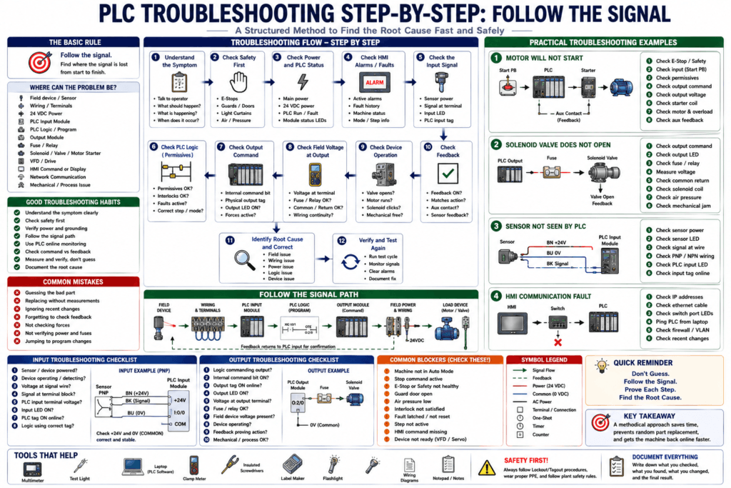
PLC troubleshooting is not about guessing which part is bad.
A good Automation Technician follows a method.
When a machine does not run, the problem could be in many places:
Field device
Sensor wiring
24 VDC power
PLC input module
PLC logic
Output module
Fuse
Relay
Solenoid
Motor starter
VFD
HMI command
Network communication
Mechanical issue
A PLC gives us a powerful advantage: we can monitor inputs, outputs, timers, counters, tags, alarms, faults, and machine states online.
But even with software, the technician must still verify the real-world electrical path.
The PLC source material explains that PLCs connect to real-world field devices through I/O sections, where input interfaces convert connected field signals into data for the processor and output interfaces convert processor data into signals for output devices.
The Basic Troubleshooting Rule
Use this simple rule:
Follow the signal.For an input problem:
Field device → Wiring → Terminal block → PLC input module → PLC tag → LogicFor an output problem:
PLC logic → Output tag → Output module → Fuse/relay/terminal → Field deviceDo not jump straight to replacing parts.
First, find where the signal is lost.
Step 1 — Understand the Symptom
Before touching the PLC program, understand the problem clearly.
Ask the operator or production team:
What is the machine supposed to do?
What is it doing instead?
When did the problem start?
Was there a recent change?
Does it happen every cycle or randomly?
Does it happen after startup?
Does it happen after a product change?
Does it happen only in Auto Mode?
Does it work in Manual Mode?
Is there an alarm on the HMI?
A clear symptom gives direction.
Bad symptom:
Machine not working.Better symptom:
Conveyor will not start in Auto Mode after box present sensor turns ON.Better symptom = faster troubleshooting.
Step 2 — Check Safety First
Before troubleshooting, verify the machine is in a safe condition.
Check:
Emergency stops
Safety gates
Light curtains
Safety relay status
Air pressure
Hydraulic pressure
Stored energy
Moving parts
Hot surfaces
Operator location
Lockout/tagout requirements
Never bypass or force safety circuits casually.
Safety devices protect people.
Step 3 — Check Power
Many PLC problems are actually power problems.
Check:
Main disconnect ON
Control transformer output
24 VDC power supply
PLC power LED
I/O module power
Field device power
Fuses and breakers
Power supply load capacity
Voltage under load
DC common
Grounding
A power supply can show 24 VDC with no load, but drop when a solenoid, relay, HMI, or sensor bank energizes.
The training source explains that PLC field devices connect to I/O sections and require termination points, and that modules convert field signals for the processor or output devices. If the field power is missing, the logic may look correct while the real devices still do not respond.
Technician Tip
Measure voltage at the point of use.
Example:
Do not only measure 24 VDC at the power supply.
Measure 24 VDC at the sensor, input module common, output fuse, and load.
This helps find voltage drops, blown fuses, bad terminals, or broken wires.
Step 4 — Check PLC Status
Look at the PLC and module LEDs.
Common things to check:
PLC Run LED
PLC Fault LED
Processor status
I/O module status
Communication status
Battery status if applicable
Force status
Remote I/O status
Power supply status
The PLC textbook describes PLC racks with LEDs for Run, Fault, Force, communication status, and I/O bit status indicators. These LEDs are designed to help the technician quickly identify controller and module status.
If the PLC is not in Run Mode, the outputs may not operate normally.
If the Fault LED is active, check controller fault information before changing logic.
Step 5 — Check the HMI Alarm or Fault Message
The HMI can give valuable information.
Check:
Active alarms
Fault history
Alarm time
Machine status message
Current step
Mode status
Permissive status
Interlock status
VFD fault code
Servo fault code
Communication alarm
Do not only clear the alarm.
Read it first.
The alarm may tell you exactly which permissive, feedback, communication path, or device is causing the stop.
Step 6 — Identify the Device Involved
Find the actual device connected to the problem.
Examples:
Box Present Photoeye
Door Closed Limit Switch
Motor Starter Auxiliary Contact
VFD Running Feedback
Valve Open Feedback
Air Pressure Switch
Tank Level Transmitter
Reject Solenoid
Conveyor Motor
Then identify:
Is it an input or output?
Is it discrete or analog?
Is it command or feedback?
Is it hardwired or networked?
Is it local I/O or remote I/O?
This classification prevents confusion.
Step 7 — Troubleshoot Inputs
Inputs tell the PLC what is happening.
If an input is missing, follow the input path.
Field device
    ↓
Device power
    ↓
Signal wire
    ↓
Terminal block
    ↓
PLC input terminal
    ↓
Input LED
    ↓
PLC tag
    ↓
Logic
The PLC training source states that field devices connected to inputs include switches, sensors, and relay contacts, and that the input interface converts those connected inputs into digital data for the processor.
Input Troubleshooting Checklist
1. Is the sensor powered?
2. Is the sensor detecting?
3. Does the sensor LED change?
4. Is the correct voltage present on the signal wire?
5. Is the signal reaching the terminal block?
6. Is the signal reaching the PLC input terminal?
7. Is the input common correct?
8. Does the PLC input LED turn ON?
9. Does the PLC tag change online?
10. Is the logic using the correct tag?
For PNP/NPN sensors, always verify:
Sensor type
Input module type
COM wiring
Signal wire
24 VDC and 0 VDC reference
Step 8 — Troubleshoot Outputs
Outputs command something in the real machine.
If an output device does not operate, follow the output path.
PLC logic
    ↓
Internal command bit
    ↓
Physical output tag
    ↓
Output LED
    ↓
Output terminal
    ↓
Fuse / relay / terminal block
    ↓
Field wiring
    ↓
Load device
    ↓
Feedback
The training material explains that when PLC output memory is set to 1, the output is ON and current flows to energize the load device; when set to 0, current is interrupted and the load de-energizes. It also notes that PLC outputs may use transistors, triacs, or relay contacts depending on the output type.
Output Troubleshooting Checklist
1. Is the PLC logic commanding the output?
2. Is the internal command bit ON?
3. Is the physical output tag ON?
4. Is the output LED ON?
5. Is voltage present at the output terminal?
6. Is the fuse good?
7. Is the interposing relay energizing?
8. Is voltage reaching the field device?
9. Is the common/neutral return correct?
10. Is the load device good?
11. Is feedback proving the device operated?
Important:
Output LED ON does not always mean the field device is working.
It usually means the PLC is commanding the output.
You still need to verify field voltage and load operation.
Step 9 — Check Command vs Feedback
This is one of the biggest troubleshooting concepts.
A command is what the PLC wants.
Feedback is proof that it actually happened.
Example:
Motor_Run_Command = PLC says run.
Motor_Running_Feedback = motor/starter/VFD proves running.
The PLC source material gives a strong motor example: if a PLC output remains energized while an overload or coil circuit fault prevents the contactor from actually energizing, the motor may unexpectedly start later when the fault is cleared. A safer design uses an auxiliary contact wired back to a PLC input so the PLC knows the real contactor status.
Command/Feedback Examples
| Device | Command | Feedback |
|---|---|---|
| Motor starter | Motor_Run_Command | Contactor_Aux_Feedback |
| VFD | VFD_Start_Command | VFD_Running / VFD_Fault |
| Valve | Valve_Open_Command | Valve_Open_FB |
| Cylinder | Extend_Solenoid | Extended_LS |
| Conveyor | Conveyor_Run_Cmd | Motor_Running_FB |
| Robot | Start_Command | Robot_Running / Cycle_Complete |
If command is ON but feedback is OFF, the problem is likely after the command path.
Step 10 — Go Online with the PLC
When safe and allowed, go online with the PLC.
Check:
Input tags
Output tags
Permissives
Interlocks
Fault bits
Timers
Counters
Current machine step
HMI command tags
Mode tags
Status tags
Network module status
The automation training source explains that PLC software monitor/online mode allows a technician to see the present status of addresses used in the program and trace why a supply or condition does not reach an output.
Use online monitoring to understand logic, not to guess.
Step 11 — Find What Is Blocking the Output
If an output should turn ON but does not, look for what is blocking it.
Common blockers:
Machine not in Auto Mode
Stop command active
E-stop not healthy
Guard door open
Air pressure low
Fault latched
Interlock active
Permissive missing
VFD not ready
Servo not homed
Sequence not in correct step
HMI command not active
Remote I/O faulted
A clean PLC program should make blockers easy to find.
Look for tags such as:
Permissives_OK
Interlocks_OK
Machine_Ready
No_Faults
Auto_Mode
Motor_Enable
Valve_Enable
Step_Active
Step 12 — Check Timers and Counters
Timers and counters can stop a sequence from moving forward.
Check:
Timer enable bit
Timer done bit
Timer accumulated value
Timer preset
Counter accumulated value
Counter preset
Counter done bit
Reset logic
One-shot logic
Example:
Valve command is ON.
Timer is running.
Valve feedback never turns ON.
Timer.DN turns ON.
Valve failed to open fault latches.
That fault may then block the next step.
Step 13 — Check Machine Step or Sequence
Many machines use step logic.
Check:
Current step number
Step description
Step active bit
Transition condition
Step timer
Step fault
Required feedback
Output command for that step
Example:
Machine_Step = 30
Step 30 = Wait for cylinder extended feedback
Cylinder extended input is OFF
Sequence will not advance
Now the problem is no longer “machine stuck.”
It is:
Cylinder extended feedback missing in Step 30.That is a much better troubleshooting statement.
Step 14 — Check Communication
Some devices are controlled over a network instead of hardwired I/O.
Examples:
EtherNet/IP VFD
Remote I/O rack
HMI
Servo drive
Robot controller
Barcode scanner
Vision system
SCADA
For communication issues, check:
Device powered
Ethernet link lights
Correct IP address
Correct subnet
PLC I/O tree status
Module connection status
Switch port status
Cables
Duplicate IP
VLAN
Adapter fault
Electronic keying
Your troubleshooting method should change depending on whether the device is hardwired or networked.
Step 15 — Check the Field Device Mechanically
The PLC can command an output correctly, but the machine may still fail mechanically.
Examples:
Solenoid energizes but valve is stuck
Cylinder moves slowly because air pressure is low
Motor runs but belt is broken
Photoeye works but bracket is loose
Limit switch works but actuator arm is bent
Encoder works but coupling is loose
Vacuum valve opens but cups are worn
Do not forget the mechanical side.
Automation troubleshooting is electrical + logic + mechanical + process.
Step 16 — Check for Forces
When machine behavior does not match logic, check forces.
Look for:
Input forces
Output forces
Force enabled status
Force installed warning
Controller force LED
Software force table
The PLC textbook describes processor indicators including a Force condition when input or output bits have been forced for testing purposes.
A force can make the PLC behave differently from the real field condition.
Example:
Physical input is OFF
But PLC logic sees input ON because it is forced
Always remove forces after controlled testing.
Step 17 — Check Recent Changes
Many problems happen after a change.
Ask:
Was a sensor replaced?
Was a motor replaced?
Was a VFD replaced?
Was an IP address changed?
Was a PLC program downloaded?
Was a cable moved?
Was a module inhibited?
Was wiring modified?
Was a recipe changed?
Was an HMI updated?
Was a safety device adjusted?
Recent change history often points directly to the root cause.
Step 18 — Do Not Replace Parts Too Fast
Replacing parts without proving the problem can waste time and create new faults.
Before replacing:
Measure voltage
Check signal
Verify tag
Check logic
Check output
Check field device
Check drawings
Compare with similar circuit
Document evidence
A sensor may look bad, but the actual problem could be:
No 24 VDC
Missing common
Wrong PNP/NPN replacement
Broken cable
Wrong input point
Bad terminal
Input card common issue
Practical Example: Motor Will Not Start
Symptom
Operator presses Start, but motor does not run.
Step-by-Step
1. Check HMI/drive/PLC alarm.
2. Check E-stop and safety status.
3. Check Auto/Manual mode.
4. Check Start command reaches PLC.
5. Check Stop and overload inputs.
6. Check permissives and interlocks.
7. Check Motor_Run_Command.
8. Check PLC output LED.
9. Check voltage at output terminal.
10. Check starter coil or VFD run command.
11. Check feedback: contactor aux or VFD running.
12. Check mechanical load.
Possible Conclusions
Start PB input missing
Overload contact open
VFD not ready
Output fuse blown
Starter coil open
Contactor aux feedback missing
Motor disconnect OFF
Mechanical jam
Practical Example: Solenoid Valve Does Not Open
Symptom
Cylinder does not extend.
Step-by-Step
1. Check air pressure.
2. Check machine step.
3. Check extend command bit.
4. Check interlocks.
5. Check output LED.
6. Measure voltage at solenoid connector.
7. Check common/neutral return.
8. Check solenoid coil.
9. Check valve manual override.
10. Check cylinder sensors.
11. Check mechanical binding.
Possible Conclusions
PLC never commands output
Output card point failed
Fuse blown
Solenoid coil open
No air pressure
Valve spool stuck
Cylinder sensor failed
Mechanical jam
Practical Example: Sensor Not Seen by PLC
Symptom
Photoeye detects product, but PLC input does not turn ON.
Step-by-Step
1. Check sensor power.
2. Check sensor alignment.
3. Check sensor LED.
4. Measure signal wire.
5. Check PNP/NPN type.
6. Check PLC input common.
7. Check voltage at input terminal.
8. Check input LED.
9. Check PLC input tag.
10. Check debounce/filter logic.
Possible Conclusions
Sensor not powered
Sensor misaligned
Wrong replacement sensor type
Broken wire
Missing common
Wrong input terminal
Bad input point
Logic using wrong tag
Practical Example: HMI Communication Fault
Symptom
HMI displays “PLC communication error.”
Step-by-Step
1. Check PLC power and Run status.
2. Check HMI power.
3. Check Ethernet link lights.
4. Check switch port LEDs.
5. Verify PLC IP address.
6. Verify HMI communication shortcut/path.
7. Check subnet/gateway if needed.
8. Ping PLC from laptop if allowed.
9. Check for duplicate IP.
10. Check recent network changes.
Possible Conclusions
Bad Ethernet cable
Wrong IP address
HMI shortcut points to old PLC
Switch port issue
Duplicate IP
PLC not in Run/Faulted
Network/VLAN issue
Troubleshooting Decision Tree
Use this simplified decision path:
1. Is the PLC powered and running?
   No → fix power/controller issue.
   Yes → continue.

2. Is there an HMI alarm or fault?
   Yes → follow alarm details.
   No → continue.

3. Is the required input present?
   No → troubleshoot field input path.
   Yes → continue.

4. Is the logic allowing the command?
   No → find missing permissive/interlock/fault/step.
   Yes → continue.

5. Is the output being commanded?
   No → troubleshoot program command logic.
   Yes → continue.

6. Is voltage reaching the field device?
   No → troubleshoot output module/fuse/relay/wiring.
   Yes → continue.

7. Did the device physically operate?
   No → troubleshoot device/mechanical/process issue.
   Yes → check feedback and sequence.
Automation Technician Notes
The best technician does not just ask:
Why is the machine not running?The best technician asks:
What condition is missing?
Where does the signal stop?
Is the PLC seeing the input?
Is the logic allowing the command?
Is the output turning ON?
Is field power reaching the device?
Did the device actually move or run?
Did feedback confirm it?
This approach turns a confusing breakdown into a structured investigation.
Common Mistakes in PLC Troubleshooting
1. Trusting the HMI Only
The HMI may not show the complete logic.
Go online with the PLC when needed.
2. Trusting the Output LED Only
Output LED ON does not prove the load energized.
Measure the field circuit.
3. Replacing Parts Without Measuring
Always verify power, signal, common, and wiring first.
4. Ignoring Feedback
Command ON does not mean device operated.
Feedback proves operation.
5. Not Checking Forces
Active forces can mislead troubleshooting.
6. Forgetting Recent Changes
Many faults appear after maintenance, replacement, downloads, IP changes, or wiring changes.
Key Terms
| Term | Meaning |
|---|---|
| Troubleshooting | Structured process to find a fault |
| Field Device | Real-world sensor, switch, motor, valve, etc. |
| Input | Signal coming into the PLC |
| Output | Signal commanded by the PLC |
| Command | PLC request for a device to operate |
| Feedback | Proof that the device actually operated |
| Permissive | Required condition before an action is allowed |
| Interlock | Condition that prevents an action |
| Fault | Abnormal condition requiring attention |
| HMI Alarm | Operator message showing problem status |
| Input LED | Module LED showing input signal status |
| Output LED | Module LED showing output command status |
| Online Monitoring | Viewing live PLC logic and tag status |
| Force | Manual override of PLC I/O status |
| Remote I/O | I/O modules connected over a network |
Final Thoughts
PLC troubleshooting is a skill built on method, not guessing.
A good technician follows the complete path:
Input → Logic → Output → Field Device → FeedbackWhen something fails, find where the chain breaks.
Is the PLC missing the input?
Is a permissive missing?
Is a fault blocking the output?
Is the output ON but field power missing?
Is the device commanded but feedback missing?
The more structured your method, the faster and safer your troubleshooting becomes.
The professional mindset is simple:
Do not guess.
Follow the signal.
Prove each step.
Document the root cause.