24. Electrical Noise and Grounding in PLC Panels ( 24 of 35 )
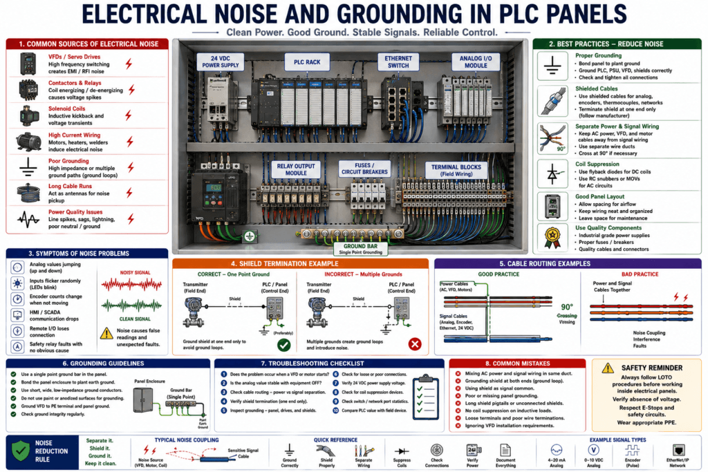
In industrial automation, a PLC panel can have a perfect program and still behave incorrectly if the electrical installation has noise or grounding problems.
Electrical noise can cause problems such as:
Random input flickering
Analog values jumping
Encoder counts changing incorrectly
Remote I/O communication drops
HMI communication faults
VFD-related interference
PLC modules faulting intermittently
Sensors triggering unexpectedly
Safety relay diagnostic faults
A PLC is designed for industrial environments, but it still depends on good installation practices. PLC systems are built for harsh conditions and immunity to electrical noise, but the wiring, grounding, shielding, and panel layout still matter.
What Is Electrical Noise?
Electrical noise is unwanted electrical energy that interferes with a signal.
In a PLC panel, signals should be clean and predictable.
Example:
Sensor OFF = 0 VDC
Sensor ON = 24 VDC
Analog signal = stable 4–20 mA
Encoder pulse = clean square wave
Ethernet communication = stable data
Electrical noise can disturb those signals.
The PLC may receive a signal that is not real.
Example:
Photoeye input flickers ON
Analog level jumps from 55% to 72%
Encoder count changes even when the shaft is stopped
Remote I/O drops connection
The PLC reacts to what it sees electrically, even if the machine did not actually change.
Common Sources of Electrical Noise
Electrical noise can come from many devices inside or near the control panel.
Common sources include:
VFDs
Servo drives
Contactors
Motor starters
Solenoid coils
Relay coils
Welders
Heaters
Large motors
Poor grounding
Improper shield termination
Long cable runs
High-current AC wiring
Damaged cables
Loose terminals
Bad power supplies
Lightning or line spikes
VFDs are one of the most common sources because they switch power very rapidly to control motor speed. VFD documentation commonly includes grounding, power conditioning, and noise-related installation requirements, including checking ground integrity periodically.
Why VFDs Can Create Noise
A VFD does not simply send a smooth sine wave to the motor.
It switches voltage very quickly.
This fast switching can create:
High-frequency noise
Common-mode noise
Voltage spikes
EMI / RFI interference
Motor cable noise
Ground current issues
This noise can couple into nearby cables.
Sensitive cables include:
Analog 4–20 mA cables
0–10 VDC signal cables
Encoder cables
Load cell cables
Ethernet cables
Thermocouple cables
RTD cables
PLC input wiring
That is why VFD motor leads should not be routed together with low-voltage signal cables.
Symptoms of Electrical Noise in PLC Systems
Electrical noise problems can be hard to diagnose because they are often intermittent.
Common symptoms:
Machine faults only when motor starts
Analog values jump when VFD runs
Photoeye input flickers randomly
Encoder position drifts
HMI loses communication after a drive starts
Remote I/O drops and reconnects
Safety relay faults without obvious field issue
PLC input LEDs flicker quickly
Counter counts too many parts
Scale or load cell readings become unstable
One important clue is timing.
Ask:
Does the problem happen when a motor starts?
Does it happen when a VFD runs?
Does it happen when a solenoid energizes?
Does it happen during high load?
Does it happen only after the machine warms up?
Does it happen only when nearby equipment operates?
Noise problems often appear when something electrical switches or changes state.
Grounding vs Common
This is one of the most important concepts.
Ground
Ground is normally used for:
Safety
Equipment bonding
Fault current path
Noise reduction
Shield reference
Panel bonding
Ground is connected to the equipment grounding system.
DC Common
DC common is the 0 VDC reference for a DC control circuit.
Example:
+24 VDC power supply positive
0 VDC power supply common
Important:
Common is not automatically the same thing as ground.
A VFD training source makes this exact point clearly: I/O terminals labeled “Common” are shared source terminals, not safety grounds.
Why Confusing Common and Ground Is Dangerous
If a technician assumes common is ground, mistakes can happen.
Example problems:
Incorrect sensor wiring
Ground loops
Noise entering signal circuits
Unexpected current paths
Input signals not working
Analog readings unstable
Damage to modules or devices
Always check the electrical drawing and device manual.
Do not randomly bond commons, shields, and grounds together without understanding the system design.
What Is a Ground Loop?
A ground loop happens when there is more than one ground path for a signal or shield.
This can allow unwanted current to flow through the shield or signal reference.
Example:
Shield grounded at transmitter end
Shield also grounded at PLC panel end
Different ground potentials exist
Current flows through shield
Noise appears on signal
Ground loops are especially problematic for:
Analog signals
Instrumentation cables
Load cells
Communication networks
Thermocouples
Long cable runs
For fieldbus cabling, one technical source explains that shields are commonly grounded at one point to avoid ground loops, and extra shield-to-ground continuity can indicate unintended shield grounding.
Shielded Cable Basics
A shielded cable has a conductive layer around the signal wires.
The shield helps protect the signal from electrical noise.
Common shielded cable applications:
4–20 mA analog signals
0–10 VDC analog signals
Encoder cables
Load cell cables
Thermocouple wiring
RTD wiring
Communication cables
VFD control wiring
High-speed pulse signals
The shield works like a protective barrier around the signal.
But only if it is installed correctly.
How Shields Are Usually Handled
Shield termination depends on the system and manufacturer instructions.
Common practice for many instrumentation signals:
Ground shield at one end only
Usually at the control panel end
Keep shield continuous
Do not use shield as signal common
Do not leave long shield pigtails
Avoid grounding shield at multiple random points
However, always follow the manufacturer’s manual and plant standard.
Some high-frequency systems may require different shield termination methods.
The key is not to guess.
Shield Drain Wire
Many shielded cables have a drain wire.
The drain wire is connected to the shield and provides an easy way to terminate the shield.
Good practice:
Drain wire connected to shield terminal or ground bar as designed
Short drain wire length
Clean termination
No loose strands
No accidental contact with signal terminals
Bad practice:
Drain wire cut off
Drain wire floating
Drain wire landed on the wrong terminal
Drain wire touching 24 VDC or signal wire
Drain wire grounded at multiple random points
A shield installed incorrectly may make noise problems worse.
Cable Separation
One of the best ways to reduce noise is to separate noisy cables from sensitive cables.
Noisy Cables
480 VAC motor power
VFD output leads
Servo motor cables
Heater power wires
Contactor load wiring
High-current AC wiring
Welding cables
Sensitive Cables
Analog signals
Encoder feedback
Load cell wiring
Thermocouple/RTD wiring
Ethernet communication
24 VDC sensor signals
High-speed counters
Instrumentation signals
Do not run them in the same wire duct if avoidable.
If they must cross:
Cross at 90 degrees
Keep crossing distance short
Avoid long parallel runs
Practical Example: VFD Noise Affecting Analog Signal
Problem
A tank level signal is stable when the machine is stopped.
When the VFD starts, the tank level jumps on the HMI.
Possible Causes
Analog cable routed beside VFD motor leads
Shield not terminated correctly
Poor VFD grounding
Poor panel grounding
Analog common problem
Loose terminal
Signal cable damaged
Wrong analog input filtering
Troubleshooting Path
1. Monitor raw analog value with VFD OFF.
2. Monitor raw analog value with VFD running.
3. Measure loop current if safe.
4. Inspect cable routing.
5. Check shield termination.
6. Check grounding and bonding.
7. Check analog input common/reference.
8. Temporarily separate signal cable if practical.
9. Verify module configuration/filtering.
10. Compare PLC value to local transmitter display.
This approach helps determine if the issue is electrical noise or actual process movement.
Practical Example: Encoder Noise
Problem
A conveyor encoder count changes even when the shaft is not moving.
Possible Causes
Encoder cable routed near VFD motor cable
Shield open or grounded incorrectly
Encoder power supply noise
Loose connector
Damaged cable
Poor grounding
Wrong input module type
Electrical noise coupling into Channel A/B
Troubleshooting Path
1. Verify encoder mechanical coupling.
2. Check encoder power.
3. Check Channel A and B wiring.
4. Watch count with shaft stopped.
5. Move motor/VFD cables away if possible.
6. Inspect shield and drain wire.
7. Check grounding.
8. Check input filter / HSC configuration.
9. Replace cable if damaged.
10. Test encoder signal with proper instrument if available.
Practical Example: Random PLC Input Flickering
Problem
A 24 VDC input flickers ON randomly.
Possible Causes
Input wire routed beside AC power
Loose common
Bad sensor cable
Induced voltage
Bad terminal
Wet junction box
Incorrect input filtering
Electrical noise from solenoid or contactor coil
Poor grounding
Troubleshooting Path
1. Check physical input LED.
2. Measure voltage at input terminal.
3. Check sensor output.
4. Check 0 VDC/common connection.
5. Inspect wire route.
6. Check for nearby VFD/contactors.
7. Check for moisture/corrosion.
8. Add proper suppression to coils if required.
9. Verify input filtering settings.
10. Correct wiring route or shielding.
Coil Suppression
Relay coils, solenoid coils, and contactor coils can generate voltage spikes when they turn OFF.
This is called inductive kickback.
Possible solutions include:
Flyback diode for DC coils
RC snubber
MOV surge suppressor
Coil suppression module
Interposing relay with suppression
Proper contactor accessories
Use the correct suppression method for the voltage and coil type.
Suppression helps protect PLC outputs and reduce noise.
VFD Grounding
A VFD should be grounded correctly according to its manual and electrical code.
Important checks:
Drive PE ground connected
Motor ground connected
Panel ground bonded
Ground conductors tight
Shielded motor cable installed if required
Ground impedance acceptable
No loose ground straps
Ground integrity periodically checked
PowerFlex documentation states that the drive safety ground/PE must be connected to system ground, ground impedance must follow applicable codes, and ground connections should be checked periodically.
Power Quality and Line Noise
Sometimes noise comes from the incoming power.
Examples:
Voltage spikes
Frequent power interruptions
Large transformer supply
Power factor correction capacitors
Lightning-related surges
Low line impedance
Ungrounded distribution issues
The PowerFlex manual lists several input power conditions that may reduce product life or damage components and recommends corrective devices such as line reactors or isolation transformers for certain conditions.
For PLC panels, poor power quality can cause:
Power supply faults
PLC resets
HMI reboots
Drive faults
Communication drops
Module errors
Safety Relay Noise and Surge Issues
Noise and surge problems can also affect safety devices.
Some safety relay fault recovery tables recommend checking wiring and validating the electrical installation to reduce noise and suppress surges when certain major faults or input pulse test faults occur.
That is a reminder that electrical noise is not just a “process signal” issue.
It can also affect diagnostic circuits and safety-related devices.
Electrical Noise Troubleshooting Mindset
When troubleshooting noise, do not only look at the PLC logic.
Ask:
When does the problem happen?
What equipment is running at that time?
Does it happen with VFD OFF?
Does it happen with VFD ON?
Does it happen when a solenoid turns off?
Does it happen when a contactor pulls in?
Does it happen only during startup?
Does it happen only after washdown?
Does it happen only in one cable route?
Noise troubleshooting is about finding the relationship between the symptom and the electrical event.
Good Grounding Practices
Good grounding practices include:
Bond control panel to plant ground
Bond doors with ground straps if required
Ground PLC chassis according to manual
Ground VFD PE terminal correctly
Ground power supplies correctly
Use proper ground bar
Keep ground connections tight
Remove paint where bonding is required
Use correct wire size
Avoid using shield as safety ground
Check ground integrity periodically
Grounding should be intentional, documented, and inspected.
Good Shielding Practices
Good shielding practices include:
Use shielded cable for analog and high-speed signals
Terminate shield according to manual
Avoid long shield pigtails
Do not use shield as signal common
Keep shield continuous through junctions if required
Avoid multiple random shield grounds
Separate shield drains from power terminals
Label shield terminals
Bad shield practices can create unstable values and intermittent issues.
Good Wire Routing Practices
Good wire routing practices include:
Separate high-voltage power and low-voltage signals
Keep VFD motor leads away from analog/encoder/network cables
Use separate wire duct when possible
Cross power and signal cables at 90 degrees
Avoid long parallel runs
Keep Ethernet away from power wiring
Use proper cable glands and strain relief
Protect cables from mechanical damage
Good routing prevents future faults.
Grounding and Shielding Are Not the Same
This is important:
Grounding = safety and reference bonding
Shielding = noise protection for signal cables
They work together, but they are not the same thing.
A shield may connect to ground, but the shield is not a replacement for a proper ground conductor.
Analog Noise vs Bad Scaling
Sometimes a technician sees an unstable analog value and assumes scaling is wrong.
But scaling problems and noise problems look different.
Bad Scaling
Value is consistently wrong
Example: gauge says 50 PSI, HMI says 25 PSI
Noise Problem
Value jumps or fluctuates
Example: HMI jumps from 50 PSI to 70 PSI when VFD runs
Different symptoms, different troubleshooting path.
Network Noise and Communication Drops
Ethernet communication problems may be caused by:
Bad cable
Poor connector
Electrical noise
Grounding issue
Switch port problem
Power issue
Cable routed near high-voltage wiring
IP conflict
Managed switch errors
Industrial switch documentation notes that front-panel status indicators help with troubleshooting, and port statistics can show errors; damaged cables may cause packet errors or links that repeatedly drop and recover.
For an Automation Technician, switch diagnostics can be very useful when communication faults appear intermittent.
Quick Field Checklist: Noise and Grounding
When you suspect noise or grounding issues, check:
1. Does the problem happen when a VFD runs?
2. Does it happen when a contactor or solenoid switches?
3. Are analog/encoder cables routed near motor leads?
4. Are shields connected correctly?
5. Is the panel ground solid?
6. Are VFD and motor grounds correct?
7. Are commons and grounds being confused?
8. Are terminals tight?
9. Are cables damaged?
10. Are input filters configured correctly?
11. Are coil suppressors installed where needed?
12. Are switch port errors increasing?
13. Is the 24 VDC power supply stable?
14. Are there signs of water, corrosion, or heat?
Automation Technician Notes
For an Automation Technician, electrical noise and grounding problems require patience.
Do not immediately change PLC logic.
Follow the evidence:
Signal behavior
Timing of the fault
Equipment running at the time
Cable routing
Grounding
Shielding
Power quality
Module diagnostics
Network diagnostics
The key question is:
What electrical event happens right before the problem appears?That question often leads you to the source.
Key Terms
| Term | Meaning |
|---|---|
| Electrical Noise | Unwanted electrical interference affecting signals |
| EMI | Electromagnetic interference |
| RFI | Radio-frequency interference |
| Ground | Safety/equipment bonding reference |
| DC Common | 0 VDC reference for control circuits |
| Ground Loop | Unwanted current path through multiple grounds |
| Shielded Cable | Cable designed to reduce noise pickup |
| Drain Wire | Wire connected to cable shield |
| VFD Noise | Electrical interference caused by drive switching |
| PE Ground | Protective earth ground |
| Inductive Kickback | Voltage spike from de-energizing a coil |
| Snubber | Suppression device for coils or switching noise |
| Line Reactor | Device used to reduce power-line issues with drives |
| Analog Noise | Interference causing unstable analog values |
| Signal Integrity | Quality and reliability of electrical signal |
Final Thoughts
Electrical noise and grounding problems can create some of the hardest PLC troubleshooting situations.
A machine may look like it has a bad sensor, bad PLC input, bad analog module, bad HMI, or bad logic, when the real problem is electrical noise or poor grounding.
For an Automation Technician, the best approach is:
Separate power and signal wiring.
Ground equipment correctly.
Terminate shields properly.
Check VFD installation.
Use coil suppression.
Verify cable routing.
Follow the signal from field device to PLC.
A clean electrical installation makes the PLC program more reliable.
A poor installation creates random faults that are difficult to troubleshoot.
The professional mindset is simple:
Good grounding protects the system.
Good shielding protects the signal.
Good cable routing prevents noise before it becomes a fault.