23. PLC Installation Best Practices ( 23 of 35 )
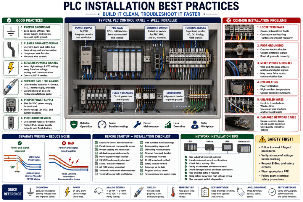
A PLC program can be well written, but if the PLC system is poorly installed, the machine can still have problems.
Many PLC issues are not caused by bad ladder logic.
They can come from:
Poor grounding
Loose wiring
Bad terminal connections
Electrical noise
Incorrect power supply wiring
Poor panel layout
Overheating
Wrong fuse protection
Mixed AC/DC wiring
VFD noise
Bad communication cable
Missing labels
Poor documentation
A PLC installation should be designed so the controller can operate reliably in a real industrial environment.
Rockwell documentation repeatedly separates installation concerns into areas such as mounting, grounding, power wiring, I/O wiring, EMC/noise practices, and safety warnings. For example, the PowerFlex manual table of contents lists installation/wiring topics including mounting considerations, grounding requirements, power wiring, I/O wiring recommendations, and EMC instructions; the Guardmaster safety relay manual similarly emphasizes installation, enclosure considerations, heat prevention, power, ground, and wiring requirements.
Why PLC Installation Matters
A PLC depends on clean power, solid wiring, correct grounding, and stable communication.
If the installation is poor, the symptoms can look like logic problems.
Examples:
Random inputs turning ON
Analog values jumping
HMI communication dropping
VFD faults
Remote I/O connection losses
Outputs not energizing
PLC modules faulting
Sensor signals disappearing
Intermittent machine stops
A good Automation Technician must understand that PLC troubleshooting is not only online monitoring.
It is also physical inspection, voltage checks, grounding checks, wiring verification, and documentation review.
1. Use the Correct Enclosure
The PLC should be mounted inside an enclosure suitable for the environment.
The enclosure protects the PLC from:
Dust
Moisture
Washdown
Chemical exposure
Heat
Vibration
Accidental contact
Mechanical damage
Electrical hazards
In industrial plants, the enclosure type matters.
Example:
Dry electrical room panel
Washdown production area panel
Outdoor panel
Dusty packaging area panel
High-temperature area
Corrosive chemical area
A PLC panel in a wet washdown area should not be treated the same as a PLC panel inside a clean MCC room.
Technician Note
When troubleshooting intermittent PLC problems, inspect the enclosure.
Look for:
Water intrusion
Condensation
Loose door gasket
Missing gland seals
Dust buildup
Corrosion
Heat marks
Damaged cable entries
Open knockouts
Improper ventilation
Water and corrosion can create strange input, output, and communication issues.
2. Control Panel Temperature
Heat is one of the enemies of electronic equipment.
A PLC panel should have proper thermal management.
Check:
Panel ambient temperature
Device heat generation
Power supply heat
VFD heat
Spacing around modules
Ventilation
Fans
Filters
Air conditioner
Heat exchanger
Sun exposure
The Guardmaster safety relay manual specifically includes Help Prevent Excessive Heat as part of its installation chapter, which is a good reminder that enclosure temperature is not a minor detail in control system reliability.
Common Heat-Related Symptoms
PLC faults after machine runs for a while
Power supply shuts down intermittently
Communication modules drop out
Analog values become unstable
HMI freezes or reboots
VFD faults during high load
Panel devices feel hot
Heat problems may appear only after the machine has been running long enough for the panel temperature to rise.
3. Mount Components with Proper Spacing
Do not pack PLC components too tightly.
PLC modules, power supplies, drives, relays, and communication devices need space for:
Airflow
Heat dissipation
Wire bending radius
Future maintenance
Terminal access
Module replacement
Clear labeling
Safe troubleshooting
A crowded panel is harder to troubleshoot and easier to overheat.
Good panel layout keeps critical components accessible.
4. Separate Power Wiring and Control Wiring
One of the most important installation practices is separating noisy power wiring from sensitive control wiring.
Keep these separated when possible:
480 VAC motor power wiring
VFD output wiring
Contactor load wiring
Heater load wiring
24 VDC control wiring
PLC input wiring
Analog signal wiring
Ethernet communication cables
Encoder cables
Instrumentation cables
VFD motor leads and high-current AC wiring can induce noise into low-voltage control and analog signals.
The PowerFlex manual treats power wiring, I/O wiring recommendations, and EMC instructions as separate installation topics, which reinforces that drive power wiring and control wiring must be handled carefully in industrial panels.
Practical Rule
Do not run this:
VFD motor leadsin the same wire duct as this:
4–20 mA analog input
Encoder signal
Ethernet cable
24 VDC sensor wiring
If they must cross, cross them at a 90-degree angle when possible.
5. Grounding Must Be Correct
Grounding is not only for safety.
It also helps reduce noise and stabilize control systems.
Grounding affects:
Personnel safety
Equipment protection
Noise reduction
Shield performance
Communication reliability
Analog signal stability
EMC performance
Industrial manuals commonly include grounding as a dedicated installation topic. For example, the PowerFlex manual lists General Grounding Requirements, and the Guardmaster safety relay manual lists Power, Ground, and Wire Wiring Requirements plus a specific grounding section.
Grounding Checks
When inspecting a PLC panel, check:
Panel ground bonded to plant ground
DIN rail bonded if required
PLC chassis grounded
Power supply grounded
VFD grounded
Shield drains terminated correctly
No loose ground wires
No painted surface blocking bond
Ground lugs tight
Correct wire size
A poor ground can create intermittent problems that are very hard to diagnose.
6. Use Shielded Cable Where Required
Sensitive signals often need shielded cable.
Examples:
Analog 4–20 mA signals
Thermocouple signals
RTD signals
Encoder cables
VFD control signals
Communication cables
Load cell cables
High-speed pulse signals
The shield helps protect the signal from electrical noise.
But the shield must be terminated correctly.
A shield that is cut off, floating, grounded incorrectly, or grounded at many uncontrolled points may not protect the signal well.
Technician Note
If an analog value is jumping, do not only check scaling.
Also check:
Cable shield
Ground connection
Wire routing
Nearby VFD wiring
Loose terminals
Signal common
Module configuration
Transmitter grounding
7. Use Correct Power Supply Sizing
A 24 VDC power supply must be sized for the total control load.
Loads may include:
PLC CPU
I/O modules
Sensors
Relays
Solenoids
HMI
Network switch
Safety relay
Encoders
Analog transmitters
Remote I/O
Stack lights
If the power supply is undersized, symptoms may include:
Voltage drops when outputs energize
PLC resets
Sensors drop out
Relays chatter
HMI reboots
Input signals become unstable
Power supply shuts down
Always check both voltage and current capacity.
8. Protect Circuits with Fuses or Breakers
Control circuits should be protected.
Protection devices help prevent wiring damage and equipment damage during faults.
Examples:
Main control fuse
Power supply fuse
PLC output group fuse
Sensor circuit fuse
Solenoid circuit fuse
HMI fuse
Network switch fuse
Analog loop fuse if applicable
The PowerFlex installation section includes fuses and circuit breakers as a dedicated topic, which is a reminder that overcurrent protection is part of proper industrial installation, not an afterthought.
Technician Note
When an output does not energize, do not stop at the PLC output LED.
Check:
Output command
Output LED
Output terminal voltage
Fuse
Terminal block
Field power
Common
Load device
A blown fuse can make a good PLC output look like a bad output.
9. Label Wires, Terminals, and Devices
Good labeling makes troubleshooting faster.
A clean installation should identify:
Wire numbers
Terminal block numbers
PLC slot and point
Sensor tag
Output device tag
Power supply terminals
Fuse numbers
Relay numbers
Ethernet ports
Cable destinations
Panel name
Machine area
Poor labeling causes wasted time.
Example:
Sensor cable enters panel
No wire number
No terminal label
No drawing reference
No tag name
Now the technician must trace everything manually.
Good labels save time during breakdowns.
10. Keep Drawings Updated
Electrical drawings are part of the installation.
A PLC panel without updated drawings is harder to troubleshoot.
Good drawings should show:
Power distribution
Control voltage
PLC rack layout
I/O wiring
Terminal blocks
Field device wiring
Network connections
Safety circuits
Fuse numbers
Wire numbers
Grounding
Panel layout
Device tags
If changes are made in the field, the drawings should be updated.
A good technician documents modifications.
11. Use Proper Terminal Blocks
Terminal blocks organize field wiring.
They also make testing easier.
Good terminal block practices:
Use correct terminal rating
Separate AC and DC terminals
Separate analog terminals when needed
Use jumpers correctly
Label terminals clearly
Use ferrules when appropriate
Tighten terminals correctly
Leave service loops where practical
Provide test points when needed
Loose terminals are a common cause of intermittent faults.
12. Check Wire Ferrules and Terminations
Bad terminations cause real problems.
Inspect for:
Loose wire strands
Over-crimped ferrules
Under-crimped ferrules
Wire insulation inside clamp
Bare copper exposed
Broken conductor
Wrong wire gauge
Multiple wires under one terminal when not allowed
Loose screw terminals
Poor spring terminal insertion
A wire may look connected but still have a poor electrical connection.
13. Keep AC, DC, Analog, and Network Wiring Organized
A professional panel layout separates wiring by function.
Example:
High voltage AC power wiring
24 VDC control wiring
PLC digital I/O wiring
Analog/instrumentation wiring
Ethernet/network wiring
Safety wiring
VFD/motor wiring
This improves:
Reliability
Noise immunity
Troubleshooting speed
Safety
Future modifications
A messy panel may work today but fail later.
14. Be Careful with VFDs
VFDs are a common source of electrical noise.
They require special attention for:
Grounding
Motor lead routing
Shielded motor cable
Line filters
Output filters
Control wiring separation
EMC practices
Correct braking resistor wiring
Communication cable routing
The PowerFlex manual includes EMC instructions and I/O wiring recommendations in its installation chapter, which is a strong reminder that drive installation directly affects the rest of the control system.
Common VFD Noise Symptoms
Analog input fluctuates when motor runs
Encoder count jumps
HMI communication drops when drive starts
PLC input flickers
Sensor false triggers
Remote I/O loses connection
If a problem happens only when a VFD runs, suspect noise, grounding, routing, or shielding.
15. Plan the Network Installation
Modern PLC panels often include Ethernet communication.
Network installation should consider:
Industrial Ethernet switch
PLC port
HMI port
Remote I/O port
VFD network port
IP addressing
Cable labeling
Patch panel
Shielded cable if needed
Fiber uplinks
VLANs if used
Ring topology if used
Managed switch diagnostics
For industrial switches, Rockwell documentation notes that front-panel status indicators provide troubleshooting information and that port statistics can be viewed through browser interface, CLI, or SNMP; it also warns that damaged cables can cause packet errors or links that repeatedly drop and recover.
Network Technician Note
When communication drops, check:
Cable condition
RJ45 connector
Switch port status
Link/activity LEDs
Port errors
IP address conflict
Duplicate device name
VLAN
Fiber link
Power to switch
Grounding/noise
Do not immediately assume the PLC or HMI is bad.
16. Provide Service Access
A good PLC panel should allow safe and practical troubleshooting.
Technicians need access to:
PLC status LEDs
I/O module LEDs
Power supply terminals
Fuses
Ethernet ports
Terminal blocks
Relay modules
VFD keypad
HMI cable
USB/programming ports
Ground bar
Panel drawings
If the panel is too crowded or poorly arranged, troubleshooting becomes slower and riskier.
17. Keep Safety Circuits Clear and Documented
Safety circuits should be easy to identify and verify.
Examples:
Emergency stop
Safety relay
Light curtain
Gate switch
Safety outputs
Dual-channel inputs
Reset circuit
Muting signals
EDM feedback
Rockwell safety relay documentation highlights that installation, configuration, operation, and maintenance require trained personnel following applicable codes, laws, and standards; it also identifies shock, burn, and arc flash hazards as safety considerations.
Important Safety Note
Never treat a safety circuit like normal PLC logic.
Safety devices protect people.
Do not bypass, jumper, force, or modify safety circuits without proper authorization, risk assessment, and plant procedure.
18. Verify I/O Before Startup
Before commissioning a PLC system, verify every input and output.
Input Verification
Activate each sensor
Check input LED
Check PLC tag online
Confirm correct tag name
Confirm correct drawing reference
Confirm NO/NC behavior
Confirm PNP/NPN wiring
Output Verification
Command each output safely
Check output LED
Check voltage at terminal
Check relay/solenoid/contactor operation
Confirm device action
Confirm feedback if available
This prevents wrong-wire and wrong-tag problems.
19. Document IP Addresses and Device Names
For Ethernet systems, record:
PLC IP address
HMI IP address
Remote I/O IP address
VFD IP address
Switch IP address
Subnet mask
Gateway
Device name
Switch port location
Panel location
Cable ID
This helps future troubleshooting.
Example:
PLC: 10.0.113.159
HMI: 10.0.113.xxx
Switch: Cuarto 1
Port: Gi1/3
A simple network map can save hours.
20. Final Installation Checklist
Before startup, check:
Panel enclosure correct for environment
PLC securely mounted
Modules seated correctly
Power supply voltage correct
24 VDC load capacity verified
Grounding complete
Fuses/breakers installed
AC/DC wiring separated
Analog wiring shielded
VFD wiring routed correctly
Network cables labeled
Field devices wired correctly
I/O verified point by point
Drawings updated
Panel cleaned
No loose wire strands
No tools left inside panel
Forces removed
Program backup saved
This checklist is simple, but it prevents many startup problems.
Practical Troubleshooting Example
Problem
A PLC analog input is unstable only when the conveyor VFD runs.
Possible Causes
Analog cable routed with VFD motor leads
Shield not grounded correctly
Poor panel ground
VFD not grounded properly
Analog common issue
Electrical noise entering signal
Input module configuration issue
Troubleshooting Path
1. Monitor analog raw value with VFD stopped.
2. Monitor analog raw value with VFD running.
3. Inspect analog cable route.
4. Inspect shield termination.
5. Check VFD grounding.
6. Check panel grounding.
7. Check separation between power and signal wiring.
8. Verify module configuration.
9. Compare with meter at transmitter.
10. Correct routing/grounding/shielding as needed.
This is a typical installation-related PLC problem.
Practical Troubleshooting Example 2
Problem
Remote I/O randomly drops communication.
Possible Causes
Damaged Ethernet cable
Loose RJ45 connector
Bad switch port
Electrical noise
Poor grounding
IP conflict
Switch power issue
Cable routed near high-voltage wiring
Troubleshooting Path
1. Check switch port LEDs.
2. Check port error counters if managed switch is available.
3. Replace/test patch cable.
4. Inspect connector condition.
5. Verify IP address.
6. Check power to remote I/O.
7. Check cable route.
8. Check grounding/noise sources.
9. Review switch diagnostics.
Automation Technician Notes
For an Automation Technician, PLC installation best practices are part of troubleshooting.
A clean PLC installation should answer these questions clearly:
Where does this wire go?
What device does this input represent?
What voltage should be here?
Where is the common?
Where is the fuse?
What output controls this device?
Where is the feedback?
What network port is this cable connected to?
What drawing page shows this circuit?
If the panel cannot answer these questions, troubleshooting becomes much harder.
Key Terms
| Term | Meaning |
|---|---|
| Enclosure | Panel/cabinet that protects control equipment |
| Grounding | Electrical reference and safety bonding system |
| Shielded Cable | Cable with shield layer used to reduce electrical noise |
| EMC | Electromagnetic compatibility |
| Electrical Noise | Unwanted electrical interference |
| DIN Rail | Metal rail used to mount control components |
| Terminal Block | Connection point for field wiring |
| Control Power | Power used for PLC, relays, sensors, and controls |
| Field Power | Power used by field devices and loads |
| Analog Signal | Variable signal such as 4–20 mA or 0–10 V |
| Remote I/O | I/O modules located away from the main PLC |
| Overcurrent Protection | Fuses/breakers used to protect circuits |
| Ground Bar | Common grounding point in a panel |
| Panel Layout | Physical arrangement of devices inside enclosure |
Final Thoughts
PLC installation best practices are not only for engineers or panel builders.
They are very important for Automation Technicians because many “PLC problems” are actually installation problems.
A reliable PLC system needs:
Good power
Good grounding
Good wiring
Good separation
Good shielding
Good labeling
Good documentation
Good network practices
Good thermal management
The better the installation, the easier the troubleshooting.
The professional mindset is simple:
Good installation prevents future faults.
Good documentation reduces downtime.
Good wiring makes troubleshooting faster.
A PLC program controls the machine, but the installation determines how reliably that control system survives in the real industrial world.