22. Sequencers and Shift Registers ( 22 of 35 )
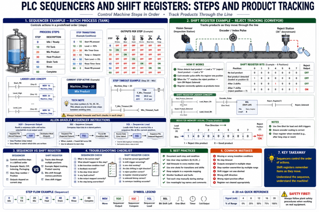
In many PLC programs, the machine does not only turn devices ON and OFF randomly.
The machine often needs to follow a specific order.
For example:
Step 1: Start conveyor
Step 2: Detect product
Step 3: Stop conveyor
Step 4: Extend pusher
Step 5: Retract pusher
Step 6: Release product
This type of control is called sequencing.
A sequencer helps the PLC move through a predefined list of steps.
A shift register helps the PLC track items as they move through a machine.
Simple way to understand it:
Sequencer = controls steps in order
Shift Register = tracks product movement through positions
The PLC textbook material explains sequencers using the historical idea of a drum sequencer, where a rotating drum actuated switches in a predefined pattern. It also describes Allen-Bradley sequencer instructions such as SQO, SQC, and SQL, where the instruction uses indexed memory locations, length, position, and masks to control or compare groups of bits during a sequence.
What Is a PLC Sequencer?
A PLC sequencer is logic that moves a machine through a series of steps.
Each step has specific outputs, actions, or conditions.
Example:
Step 0 = Idle
Step 1 = Fill tank
Step 2 = Mix product
Step 3 = Heat product
Step 4 = Drain tank
Step 5 = Complete
A sequencer is useful when the machine operation must happen in a known order.
Real Industrial Examples of Sequencers
Sequencers are used in:
Batch processes
Clean-In-Place systems
Packaging machines
Indexing machines
Palletizers
Filling machines
Washing cycles
Robot cell coordination
Conveyor zones
Automatic startup and shutdown sequences
A strong example from the PLC source material is a Clean-In-Place / CIP system, where pumps and valves must operate in a well-defined sequence to clean a vessel. The example describes multiple timed steps and nine discrete outputs controlling final control elements such as pumps and valves.
Simple Sequencer Example: Pneumatic Cylinder
Imagine a machine that pushes a box using a pneumatic cylinder.
Inputs
DI_Start_PB
DI_Box_Present
DI_Cylinder_Extended
DI_Cylinder_Retracted
DI_Reset
Outputs
DO_Extend_Solenoid
DO_Retract_Solenoid
DO_Cycle_Complete_Light
Sequence
Step 0: Idle
Step 10: Wait for box
Step 20: Extend cylinder
Step 30: Wait for extended feedback
Step 40: Retract cylinder
Step 50: Wait for retracted feedback
Step 60: Cycle complete
This is a basic sequencer.
Step-Based Logic
A common way to build a sequencer is with a step number.
Example tag:
Machine_StepThe PLC moves from step to step.
Example:
Machine_Step = 0   Idle
Machine_Step = 10  Wait for box
Machine_Step = 20  Extend cylinder
Machine_Step = 30  Wait extended
Machine_Step = 40  Retract cylinder
Machine_Step = 50  Wait retracted
Machine_Step = 60  Complete
Using numbers like 0, 10, 20, 30 is useful because you can insert future steps between them.
Example:
Step 25 = Delay before extend completeSequencer Output Concept
A sequencer output instruction can turn different outputs ON or OFF depending on the current step.
Example:
| Step | Conveyor | Fill Valve | Mixer | Drain Valve |
|---|---|---|---|---|
| 0 Idle | OFF | OFF | OFF | OFF |
| 10 Fill | OFF | ON | OFF | OFF |
| 20 Mix | OFF | OFF | ON | OFF |
| 30 Drain | OFF | OFF | OFF | ON |
| 40 Complete | OFF | OFF | OFF | OFF |
In this concept, each step has a pattern of output states.
The textbook describes SQO as reading a sequence of memory words and writing selected bits to a destination, with a mask determining which bits are copied. It also describes the sequencer position as an index that points to the active memory word.
SQO — Sequencer Output
In Allen-Bradley PLCs, SQO means Sequencer Output.
Simple explanation:
SQO reads a stored pattern of bits
Then writes those bits to an output word or destination tag
The SQO instruction usually includes:
File / Array = stored sequence patterns
Mask = which bits are allowed to be written
Destination = where the output pattern goes
Control = internal sequencer control structure
Length = number of steps
Position = current step
The important concept is:
Position selects which pattern is active.Mask Concept
The mask tells the sequencer which bits matter.
Example:
Mask = 1111This means the sequencer controls four bits.
Example:
Bit 0 = Conveyor
Bit 1 = Fill Valve
Bit 2 = Mixer
Bit 3 = Drain Valve
If a mask bit is included, the sequencer can write to that destination bit.
If a mask bit is ignored, the sequencer does not control that bit.
The source material explains that the mask allows the SQO instruction to write only selected bits of the destination word instead of always writing all 16 bits.
SQC — Sequencer Compare
SQC means Sequencer Compare.
Simple explanation:
SQC compares actual input conditions to an expected pattern.Example:
Expected condition:
Valve_Open_FB = ON
Pump_Running_FB = ON
Tank_Level_OK = ON

Actual inputs match expected pattern:
SQC found bit turns ON
The PLC source material explains that SQC reads from a file and compares selected bits against input bits. When the selected conditions match, the SQC found bit can be used to advance the sequence.
This is useful when a sequence should only move forward after the correct feedback is present.
SQL — Sequencer Load
SQL means Sequencer Load.
Simple explanation:
SQL loads live data into a sequence file or memory location.It is like the opposite of SQO.
Instead of reading stored data and writing to outputs, SQL can store live process data into indexed memory.
The source material describes SQL as taking data from a source and writing it into an indexed register according to the position value. It notes that this can be useful for data logging or recording process data at different times.
Sequencer vs State Machine
A sequencer and a state machine are related, but they are not always the same thing.
Sequencer
A sequencer usually follows a fixed order:
Step 1 → Step 2 → Step 3 → Step 4Best for:
Batch cycles
Timed operations
Known repeated steps
CIP cycles
Simple indexing
State Machine
A state machine can make more flexible decisions.
Example:
Idle
Starting
Running
Holding
Faulted
Resetting
Stopping
Best for:
Machines with multiple modes
Manual/Auto logic
Fault handling
Recovery logic
Complex transitions
For modern PLC programming, many technicians prefer building sequencer-style logic using a state machine because it is easier to read and troubleshoot.
What Is a Shift Register?
A shift register is used to move bits through memory positions.
Simple idea:
Each machine index or conveyor pulse shifts the data one position.A shift register is very useful when a product moves through a machine and the PLC needs to remember something about that product.
Example:
Product inspected at station 1
Product moves down conveyor
Reject station is 10 positions away
PLC remembers which product must be rejected
Shift Register Example: Reject Tracking
Imagine a vision system checks bottles on a conveyor.
If a bottle is bad, the PLC needs to reject it later.
Problem
The reject station is not at the same location as the inspection station.
Vision camera detects bad bottle here
Reject solenoid is 36 inches downstream
The PLC needs to track the bad bottle as it moves.
A shift register can store:
1 = reject this product
0 = good product
Each encoder pulse or conveyor index shifts the bits forward.
When the reject bit reaches the reject station position, the PLC turns ON the reject solenoid.
Shift Register Concept
Example:
Initial:
[1] [0] [0] [0] [0] [0]

After one shift:
[0] [1] [0] [0] [0] [0]

After two shifts:
[0] [0] [1] [0] [0] [0]
The 1 represents a bad product traveling through the machine.
When the 1 reaches the reject output position:
Turn ON Reject_SolenoidBit Shift Left / Bit Shift Right
PLC platforms often have shift instructions.
Common concepts:
Bit Shift Left
Bit Shift Right
Shift Register
FIFO
Product tracking array
A bit shift moves bit values in one direction.
Example:
Before shift:
Bit 0 = 1
Bit 1 = 0
Bit 2 = 0

After shift:
Bit 0 = 0
Bit 1 = 1
Bit 2 = 0
The bit moved from position 0 to position 1.
What Triggers the Shift?
A shift register needs a shift trigger.
Common shift triggers:
Encoder pulse
Conveyor index complete
Product detected pulse
Machine cycle complete
Pusher stroke complete
Starwheel index
Timing pulse
The shift should usually happen once per real movement step.
Important:
Use a one-shot so one movement creates one shift.Without a one-shot, the shift register may shift many times from one event.
Sequencer vs Shift Register
| Feature | Sequencer | Shift Register |
|---|---|---|
| Main purpose | Control steps in order | Track data through positions |
| Common use | Batch, CIP, machine cycle | Product tracking, reject timing |
| Data movement | Step position changes | Bits shift through memory |
| Typical trigger | Step complete condition | Conveyor index or encoder pulse |
| Example | Fill → Mix → Drain | Bad product moves to reject station |
| Troubleshooting focus | Current step and transition | Bit position and shift trigger |
Practical Example: Packaging Reject System
Inputs
DI_Product_Detected
DI_Bad_Product
DI_Encoder_Pulse
DI_Reset
Outputs
DO_Reject_SolenoidInternal Tags
Reject_Shift_Register
Reject_Load_Bit
Reject_Trigger_Position
Encoder_Pulse_OS
Operation
1. Product passes inspection station.
2. If product is bad, load a 1 into the shift register.
3. If product is good, load a 0.
4. Each encoder pulse shifts the register.
5. When the reject bit reaches the reject station position, turn ON reject solenoid.
6. Reset/clear register when needed.
Practical Example: Indexing Table
An indexing table moves one station at a time.
Each station may have a part status.
Station 1 = Load
Station 2 = Inspect
Station 3 = Fill
Station 4 = Cap
Station 5 = Reject
A shift register can track:
Part present
Part good/bad
Part filled
Part capped
Reject required
Each time the table indexes, the data shifts to the next station.
Practical Example: CIP Sequencer
A CIP sequence may have steps like:
Step 10: Pre-rinse
Step 20: Drain
Step 30: Caustic wash
Step 40: Circulate at temperature
Step 50: Return wash
Step 60: Acid wash
Step 70: Final rinse
Step 80: Complete
Each step may control:
Supply pump
Return pump
Drain valve
Caustic valve
Acid valve
Rinse valve
Temperature control
Timer preset
This is exactly the type of application where a sequencer can help organize outputs and steps.
Important: Sequencer Must Have Step Conditions
A sequencer should not blindly move to the next step without checking conditions.
Common step-complete conditions:
Timer done
Sensor feedback received
Valve open feedback
Motor running feedback
Tank level reached
Temperature reached
Operator acknowledgment
No fault active
Example:
Step 20 = Extend cylinder
Move to Step 30 only when:
DI_Cylinder_Extended = ON
Better logic:
Step 20 active
AND Extend feedback ON
AND No fault
THEN move to Step 30
Fault Handling in Sequencers
Good sequencer logic should include fault detection.
Examples:
Valve failed to open
Cylinder failed to extend
Motor failed to start
Sensor did not detect product
Step timeout
Unexpected feedback
Sequence took too long
Example:
If Step 20 is active
AND Cylinder_Extended feedback is not ON within 3 seconds
THEN Cylinder_Extend_Fault = ON
This helps troubleshooting.
Step Timeout
A step timeout prevents the machine from staying stuck forever in one step.
Example:
Step 20 commands cylinder extend.
Timer starts.
If cylinder extended feedback is not received in 3 seconds,
fault the machine.
This is one of the most important sequencer troubleshooting features.
Reset and Recovery
A sequence should have clear reset and recovery logic.
Ask:
What happens if the machine faults in Step 30?
Can the operator reset?
Does the sequence return to Idle?
Does it resume from the same step?
Does it require manual recovery?
Are outputs turned off safely?
Do not create a sequence that resets unexpectedly while equipment is still moving.
Common Sequencer Problems
1. Sequence Stuck in a Step
Possible causes:
Missing feedback
Timer not done
Wrong transition condition
Fault active
Sensor not made
Output not energizing
Step complete bit not turning ON
2. Sequence Skips a Step
Possible causes:
Transition condition already true
Step logic written incorrectly
One-shot missing
Multiple MOV instructions changing step
JMP skipping logic
Reset logic active
3. Outputs Turn ON in Wrong Step
Possible causes:
Wrong bit pattern
Wrong SQO mask
Wrong destination word
Step number mismatch
Duplicate output coil
Output mapping problem
4. Shift Register Rejects Wrong Product
Possible causes:
Wrong shift trigger
Conveyor slip
Encoder scaling wrong
Reject position offset wrong
One-shot missing
Product spacing inconsistent
Register cleared too early
Bad product bit loaded at wrong time
Troubleshooting a Sequencer
When a sequencer is not working, check:
1. What step is active?
2. What should happen in this step?
3. Which outputs should be ON?
4. Which feedback is required?
5. Is the step timer running?
6. Is the transition condition true?
7. Is a fault blocking the transition?
8. Is the sequence being reset?
9. Is the step number being overwritten?
10. Is the output mapped correctly?
Troubleshooting a Shift Register
When a shift register is not working, check:
1. Is the load bit correct?
2. Is the product good/bad signal correct?
3. Is the shift trigger occurring?
4. Is the shift trigger one-shot protected?
5. Are bits shifting in the correct direction?
6. Is the reject position correct?
7. Is the register being cleared too soon?
8. Is conveyor speed or encoder tracking correct?
9. Is the reject output timed correctly?
10. Is the solenoid physically working?
Automation Technician Notes
For an Automation Technician, the key idea is this:
Sequencers control the order of actions.
Shift registers track items through positions.
When troubleshooting a sequencer, focus on:
Current step
Required feedback
Step timer
Transition condition
Fault status
Output command
When troubleshooting a shift register, focus on:
Load bit
Shift pulse
Bit position
Tracking distance
Reject output timing
These tools are powerful, but they must be documented clearly. If the program has poor comments, a sequencer or shift register can be very difficult to troubleshoot.
Best Practices
1. Use Clear Step Names
Do not only show:
Step = 30Also create HMI text or comments:
Step 30 = Waiting for cylinder extended feedback2. Use Step Timeouts
Every motion step should have a timeout.
Example:
Cylinder extend command ON
Expected feedback within 3 seconds
3. Use One-Shots for Step Advances
Avoid advancing multiple steps in one scan unless intentionally designed.
4. Keep Output Mapping Separate
Better:
Step logic → Internal command → Physical outputExample:
Step_20_Extend_Command → DO_Cylinder_Extend5. Document Shift Register Positions
Example:
Bit 0 = Inspection station
Bit 5 = Reject station
Bit 8 = Exit sensor
Without position documentation, troubleshooting becomes painful.
Key Terms
| Term | Meaning |
|---|---|
| Sequencer | Logic that moves through predefined steps |
| Step | Current stage of the machine sequence |
| SQO | Sequencer Output instruction |
| SQC | Sequencer Compare instruction |
| SQL | Sequencer Load instruction |
| Position | Current sequencer step/index |
| Mask | Defines which bits are controlled or compared |
| Shift Register | Memory structure that shifts bits through positions |
| Bit Shift | Moving bits left or right through memory |
| Load Bit | Bit inserted into the shift register |
| Shift Trigger | Event that causes bits to move |
| One-Shot | Single-scan pulse used to prevent multiple shifts |
| Step Timeout | Fault timer for a sequence step |
| Transition | Condition that moves the sequence to the next step |
Final Thoughts
Sequencers and shift registers are powerful PLC tools for machines that require ordered actions or product tracking.
A sequencer is best when the machine must follow a series of steps, such as filling, mixing, draining, washing, indexing, or cycling.
A shift register is best when the machine needs to remember information about a product as it moves through different positions.
For an Automation Technician, the most important troubleshooting questions are:
What step is active?
What condition moves it forward?
What output should be ON?
What feedback is missing?
Is the shift register moving at the correct time?
Is the correct bit reaching the correct station?
Once you understand these questions, sequencers and shift registers become much easier to troubleshoot in real machines.