1. What Is a PLC and Why Is It Used in Industry?
What Is a PLC?
A PLC, or Programmable Logic Controller, is an industrial computer used to control machines, equipment, and automated processes.
In simple words, a PLC reads signals from field devices, makes decisions based on a program, and turns outputs ON or OFF to control the machine.
A basic PLC control system works like this:
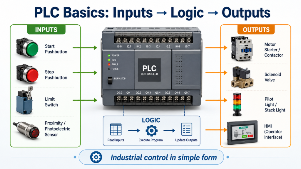
Inputs → PLC Program → OutputsFor example:
Start Pushbutton  →  PLC Logic  →  Motor Contactor
Limit Switch      →  PLC Logic  →  Solenoid Valve
Sensor            →  PLC Logic  →  Pilot Light / Alarm / VFD Command
Unlike a regular computer, a PLC is designed to work in harsh industrial environments where there may be electrical noise, vibration, heat, humidity, and continuous machine operation. The textbook describes the PLC as an industrial-grade computer used for control functions, with input/output interfaces and a control programming language designed for machine control.
Why Was the PLC Created?
Before PLCs became common, many industrial machines were controlled using hardwired relay logic.
Relay control systems used physical relays, timers, contactors, pushbuttons, limit switches, and wiring to create the control logic. This worked, but it had a major problem:
If the process needed to change, the wiring often had to change too.
That meant more downtime, more troubleshooting, and more chances for wiring mistakes.
The PLC solved this problem by moving much of the control logic from physical wiring into a programmable controller. The field devices still need to be wired, but the decision-making logic is handled by the PLC program.
Relay Logic vs PLC Logic
A relay-based control panel depends heavily on physical wiring.
A PLC-based control panel still uses wiring, but much of the logic is stored in memory as a program.
| Relay-Based Control | PLC-Based Control |
|---|---|
| Logic is created with physical wiring | Logic is created with software |
| Changes require rewiring | Changes can often be made by editing the program |
| Large panels with many relays | Smaller, cleaner control panels |
| Harder to troubleshoot complex logic | Easier to monitor logic online |
| More mechanical wear | Solid-state control and diagnostics |
Modern control systems still use relays and contactors, especially for power circuits, but the PLC usually handles the control decisions.
What Does a PLC Control?
PLCs are used in many industrial applications, including:
- Conveyors
- Pumps
- Motors
- Valves
- VFDs
- Mixers
- Packaging machines
- Tank level systems
- Safety-related machine status monitoring
- Production lines
- HMI and SCADA systems
A PLC can perform more than simple ON/OFF control. It can also handle:
- Timing
- Counting
- Math operations
- Comparisons
- Analog signal processing
- Communication with other devices
- Alarm and status logic
- Data collection
- Machine sequencing
This is why PLCs are used in almost every modern industrial environment.
Basic Parts of a PLC System
A typical PLC system has several important parts:
1. CPU / Processor
The CPU is the brain of the PLC. It runs the user program, makes logic decisions, manages memory, communicates with modules, and controls the outputs.
2. Input Modules
Input modules receive signals from field devices such as:
Pushbuttons
Selector switches
Limit switches
Proximity sensors
Photoeyes
Pressure switches
Level switches
The PLC uses these input signals to understand what is happening in the machine.
3. Output Modules
Output modules control devices such as:
Pilot lights
Relays
Solenoids
Motor starters
Contactors
Horns
VFD commands
The PLC turns outputs ON or OFF based on the logic program.
4. Power Supply
The power supply provides the correct internal power for the PLC processor and modules.
5. Programming Device
A laptop with programming software is commonly used to create, edit, monitor, upload, and download PLC programs.
How a PLC Works
A PLC operates using a repeated process called the scan cycle.
A simplified scan cycle looks like this:
1. Read Inputs
2. Execute Program Logic
3. Update Outputs
4. Perform Diagnostics and Communication
5. Repeat
This process happens continuously while the PLC is in Run Mode.
For example, imagine this simple motor control:
If Start_PB is pressed
AND Stop_PB is healthy
THEN turn on Motor_Starter
The PLC checks the input status, evaluates the logic, and updates the output.
This happens very fast, usually many times per second.
Why Are PLCs Used in Industry?
PLCs are used because they provide major advantages over traditional relay-based control systems.
1. Easier to Modify
With a PLC, many logic changes can be made in the program instead of rewiring the control panel.
Example:
Original logic:
Motor starts when Start PB is pressed.

Modified logic:
Motor starts when Start PB is pressed AND Safety Gate is closed.
In a relay system, this may require wiring changes.
In a PLC system, it may only require adding another condition in the ladder logic.
2. Easier to Troubleshoot
One of the biggest advantages for an Automation Technician is online monitoring.
With PLC software, you can often see:
Which input is ON
Which output is ON
Which rung is true
Which timer is timing
Which fault bit is active
Which permissive is missing
This makes troubleshooting faster and more organized.
Instead of guessing, the technician can follow the logic.
3. Less Hardwiring
PLCs reduce the amount of control wiring required compared to large relay panels.
This makes control panels:
Cleaner
Smaller
Easier to modify
Easier to document
Easier to troubleshoot
Field devices still need to be wired to input and output modules, but the logical relationship between devices is handled by the PLC program.
4. Better Reliability
Relay systems depend on many mechanical contacts. Mechanical devices can wear out over time.
PLCs use solid-state electronics and memory-based logic, which improves reliability when properly installed and maintained.
5. Faster Response
PLCs are designed for real-time industrial control.
That means when a field input changes, the PLC can quickly process that change and update the correct output.
This is important for high-speed machines, conveyors, packaging systems, counting applications, and automated production lines.
6. Communication Capability
Modern PLCs can communicate with many industrial devices, such as:
HMIs
VFDs
Remote I/O
SCADA systems
Other PLCs
Industrial switches
Barcode readers
Process instruments
SQL / data systems
This allows the PLC to be part of a larger automation system instead of working alone.
Simple Industrial Example
Imagine a mixer tank.
The motor should run when:
The temperature is high enough
AND the pressure is correct
OR the operator presses Manual Start
In relay logic, this requires physical wiring between switches, relays, and the motor starter.
In PLC logic, the field devices are wired to the PLC inputs, and the motor starter is wired to a PLC output.
The program decides when the motor should run.
Example logic idea:
IF Temperature_OK AND Pressure_OK
OR Manual_Start
THEN Mixer_Motor = ON
This is the power of PLC control: the same field devices can be used, but the control behavior can be changed by modifying the program.
PLC vs Regular Computer
A PLC and a personal computer are both computing devices, but they are built for different jobs.
| PLC | Regular Computer |
|---|---|
| Designed for industrial control | Designed for general computing |
| Handles real-world inputs and outputs | Usually does not directly control field devices |
| Built for harsh environments | Built for office/home environments |
| Runs control logic repeatedly | Runs many types of software |
| Uses ladder logic and industrial languages | Uses general-purpose software/programming |
| Designed for machine reliability | Designed for user interaction and applications |
A PLC is not just a computer inside a panel. It is a dedicated industrial controller designed to run machines safely, repeatedly, and reliably.
Automation Technician Notes
For a technician, understanding PLCs is not only about programming.
It is also about knowing how to troubleshoot the complete control system.
When a machine does not run, the problem could be:
Bad sensor
Broken wire
Missing 24VDC
Blown fuse
Failed output
Bad relay
Faulted VFD
Incorrect logic condition
Active interlock
Missing permissive
PLC not in Run Mode
Communication fault
A good technician does not only ask, “Why is the output not on?”
A good technician asks:
Is the PLC receiving the input?
Is the logic true?
Is the output being commanded?
Is field voltage present?
Is the controlled device working?
Is there an interlock or fault preventing operation?
That mindset is what separates guessing from real troubleshooting.
Key Terms
| Term | Meaning |
|---|---|
| PLC | Programmable Logic Controller |
| CPU | Processor that runs the PLC program |
| Input | Signal going into the PLC |
| Output | Signal controlled by the PLC |
| Field Device | Real-world device wired to the PLC |
| Ladder Logic | Common PLC programming language |
| Scan Cycle | Repeated PLC process of reading inputs, solving logic, and updating outputs |
| HMI | Human Machine Interface used by operators |
| I/O | Inputs and outputs |
| Program | Logic instructions stored in the PLC |
Final Thoughts
A PLC is one of the most important devices in industrial automation. It connects the real world of sensors, switches, motors, valves, and machines with the logic needed to control a process.
PLCs are used because they are reliable, flexible, easier to troubleshoot, and designed for industrial environments. For an Automation Technician, learning PLC fundamentals is a major step toward understanding how modern machines operate.
The better you understand the PLC, the easier it becomes to troubleshoot real equipment in the field.