3. How the PLC Scan Cycle Works
How the PLC Scan Cycle Works
The PLC scan cycle is one of the most important fundamentals to understand in industrial automation.
A PLC does not normally read an input, solve one rung, and immediately update a physical output one instruction at a time. Instead, it works in a repeated cycle called the scan cycle.
A basic PLC scan cycle can be understood like this:
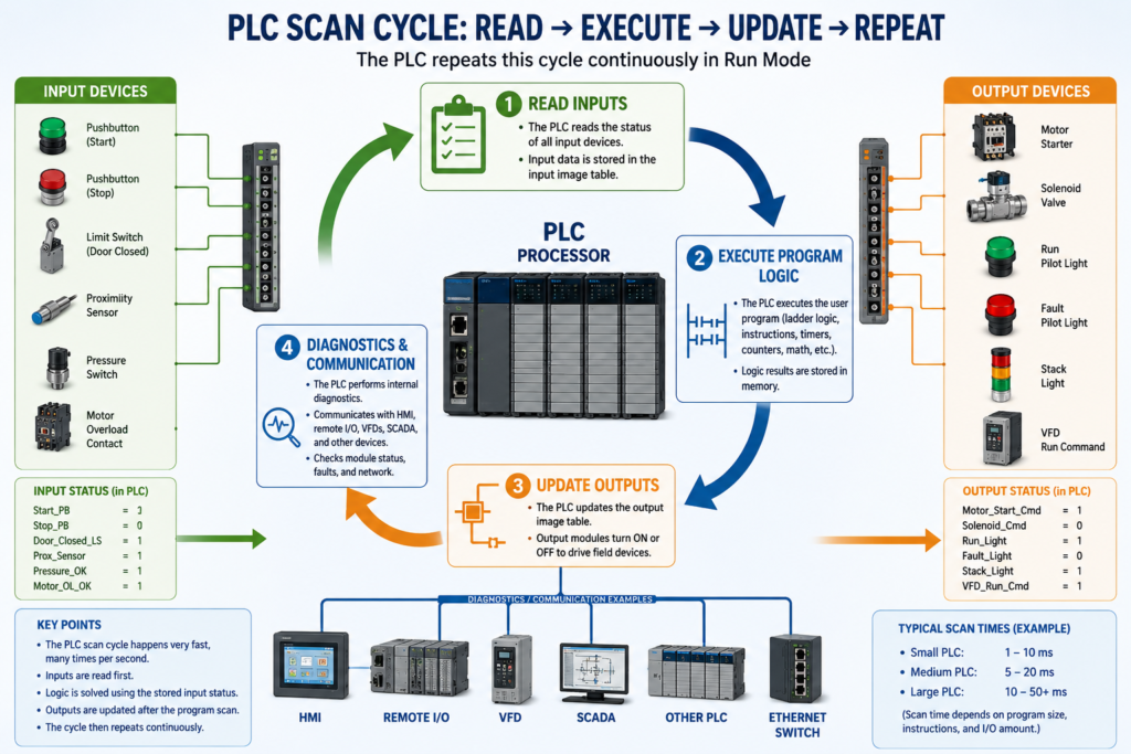
1. Read the input status
2. Execute the PLC program
3. Update the outputs
4. Perform diagnostics and communication
5. Repeat continuously
This process happens very fast, usually many times per second, while the PLC is in Run Mode.
In Programmable Logic Controllers, 6th Edition, the PLC scan is described as a repetitive process where the CPU reads inputs, executes the program logic, updates outputs, and performs diagnostic and communication tasks continuously.
Why the Scan Cycle Matters
Understanding the scan cycle helps a technician understand why PLC logic behaves the way it does.
It explains questions like:
Why is the input LED ON, but the output is not ON?
Why did the output turn ON one scan later?
Why does a one-shot only trigger once?
Why does a fast sensor sometimes get missed?
Why does the program appear true, but the field device is not energized?
Why is the HMI showing a value slightly after the PLC logic changes?
The scan cycle is the heartbeat of the PLC.
Once you understand the scan, ladder logic becomes much easier to read and troubleshoot.
1. Step One — Read Inputs
The first major step in the scan cycle is reading the physical input devices.
Input devices can include:
Pushbuttons
Selector switches
Limit switches
Proximity sensors
Photoelectric sensors
Pressure switches
Level switches
Motor overload contacts
VFD status contacts
Safety relay auxiliary contacts
The PLC input module detects whether the field device is ON or OFF.
Then the PLC stores that information in memory.
This memory area is often called the input image table, input status table, or simply the PLC’s input data.
Example:
Start_PB = ON
Stop_PB = ON
Door_Closed_LS = ON
PhotoEye_Clear = ON
Motor_OL_OK = ON
In binary logic:
ON  = 1
OFF = 0
So if a pushbutton is pressed and the input module sees voltage, the PLC records that input as a logic 1.
If the input is not active, the PLC records it as a logic 0.
Important Technician Point
During this step, the PLC is reading the actual field input status.
But after the input image is updated, the program usually solves logic using that stored input status for that scan.
That means the ladder program is normally solving based on a “snapshot” of the inputs taken at the beginning of the scan.
Simple way to think about it:
Field device changes → Input module detects it → PLC copies status into memory → Program uses that status2. Step Two — Execute the Program Logic
After reading the inputs, the PLC executes the user program.
This is where ladder logic is solved.
The CPU evaluates the instructions based on the input status, internal bits, timers, counters, data values, faults, permissives, interlocks, and commands.
A simple ladder logic idea may look like this:
Start_PB      Stop_OK      Motor_OL_OK
--] [----------] [-----------] [----------------( Motor_Run_Cmd )
The PLC evaluates the logic from left to right and top to bottom.
If the rung conditions are true, the output instruction becomes true.
If the rung conditions are false, the output instruction becomes false.
Example: Motor Start Logic
Let’s say the PLC reads these inputs:
Start_PB     = 1
Stop_OK      = 1
Motor_OL_OK  = 1
The logic becomes true:
Start_PB AND Stop_OK AND Motor_OL_OK = TRUEThen the PLC sets the internal output command:
Motor_Run_Cmd = 1But this does not always mean the physical motor starter energizes immediately at that exact instruction. In many PLC systems, the physical outputs are updated after the program execution step.
3. Step Three — Update Outputs
After the PLC finishes solving the program, it updates the output modules.
This is when the PLC sends the final output status to the physical output points.
Output devices can include:
Motor starters
Contactors
Solenoid valves
Pilot lights
Stack lights
Relays
Horns
VFD run commands
Actuators
Example:
Motor_Run_Cmd = 1At the output update step:
PLC output module turns ON
Motor starter coil energizes
Motor starts running
Or:
Solenoid_Cmd = 1Then:
PLC output module turns ON
Solenoid valve energizes
Air or fluid flow changes
Output Image Table
Just like inputs, outputs also have memory.
The PLC program writes to an output memory location. Then the output module is updated based on that memory value.
Simple concept:
PLC Logic Result → Output Memory → Output Module → Field DeviceThat is why a technician should understand the difference between:
The output bit in the PLC program
The output LED on the module
The actual voltage at the output terminal
The real field device energizing
These are related, but they are not always the same thing during troubleshooting.
4. Step Four — Diagnostics and Communication
After inputs are read, logic is solved, and outputs are updated, the PLC also performs internal tasks.
These may include:
Processor diagnostics
Module status checks
Communication with HMI
Communication with VFDs
Communication with remote I/O
Communication with SCADA
Fault monitoring
Network messaging
Program housekeeping
This is why PLCs can monitor the machine and communicate with other automation devices at the same time.
A modern PLC may communicate with:
HMI panels
Remote I/O blocks
VFDs
Servo drives
Industrial Ethernet switches
Other PLCs
SCADA systems
SQL/data collection systems
Barcode readers
Vision systems
These communication tasks are part of the overall controller operation.
Simple Scan Cycle Diagram
        ┌────────────────────┐
        │    Read Inputs      │
        └─────────┬──────────┘
                  ↓
        ┌────────────────────┐
        │ Execute PLC Logic   │
        └─────────┬──────────┘
                  ↓
        ┌────────────────────┐
        │   Update Outputs    │
        └─────────┬──────────┘
                  ↓
        ┌────────────────────┐
        │ Diagnostics / Comm  │
        └─────────┬──────────┘
                  ↓
              Repeat Scan
The PLC repeats this cycle continuously as long as it is running.
Real-World Example: Conveyor Start
Imagine a conveyor controlled by a PLC.
Input Devices
Start_PB
Stop_PB
Motor_Overload_OK
PhotoEye_Clear
E_Stop_OK
Output Devices
Conveyor_Motor_Starter
Run_Pilot_Light
Fault_Pilot_Light
PLC Logic
If Start_PB is pressed
AND Stop_PB is OK
AND E_Stop_OK is true
AND Motor_Overload_OK is true
AND PhotoEye_Clear is true
THEN Conveyor_Motor_Starter turns ON
Scan Cycle Operation
Scan Step 1 — Read Inputs
The PLC reads the field devices:
Start_PB = ON
Stop_PB = OK
E_Stop_OK = OK
Motor_Overload_OK = OK
PhotoEye_Clear = OK
Scan Step 2 — Execute Logic
The PLC solves the logic:
All permissives are true
Conveyor_Run_Cmd = ON
Scan Step 3 — Update Outputs
The PLC updates the output module:
Conveyor_Motor_Starter output turns ON
Run_Pilot_Light turns ON
Scan Step 4 — Diagnostics / Communication
The PLC updates communication and status:
HMI shows Conveyor Running
SCADA may log the status
Remote I/O status is checked
Then the scan repeats.
Why Fast Inputs Can Be Missed
One important scan-cycle concept is that a PLC must see an input long enough to capture it during the scan.
If a sensor turns ON and OFF very quickly between scans, the PLC may not detect it.
Example:
PLC scan time = 20 ms
Sensor pulse = 5 ms
The sensor may turn ON and OFF before the PLC reads the input.
Possible solutions include:
High-speed input module
Pulse-stretching logic
One-shot logic
Hardware counter
Encoder/high-speed counter module
Proper sensor adjustment
Slower mechanical target
This is why high-speed applications like encoders, fast counting, and registration sensors may require special PLC hardware or special instructions.
Input LED ON Does Not Always Mean Logic Is True
This is a very important troubleshooting point.
A technician may see the input LED ON at the PLC module and assume the logic should be true.
But the logic may still be false because:
The program is using a different tag
The input is inverted in logic
The input is mapped through buffering logic
The input is disabled by mode logic
The input is being filtered or debounced
A permissive is missing
An interlock is active
A fault is latched
The PLC is not in Run Mode
The module is faulted
The input LED only tells you that the module sees the electrical signal.
It does not automatically mean the final machine command should be ON.
Output LED ON Does Not Always Mean the Device Is Working
The same idea applies to outputs.
If the PLC output LED is ON, the PLC is commanding the output.
But the field device may still not operate.
Possible causes:
Blown output fuse
Missing field power
Bad relay
Bad solenoid coil
Bad contactor coil
Broken wire
Loose terminal
Failed output point
Wrong voltage
Bad neutral or common
Mechanical problem in the device
VFD fault blocking operation
This is why PLC troubleshooting must include both the program and the electrical circuit.
A good technician checks:
PLC command
Output LED
Voltage at output terminal
Voltage at field device
Return/common/neutral
Device coil resistance
Mechanical condition
Feedback signal
Scan Cycle and Ladder Logic Order
The order of ladder logic matters.
The PLC solves the program in a defined order.
Usually:
Top to bottom
Left to right
Routine by routine
Task by task
This means a bit can be turned ON in one rung and used later in another rung during the same scan.
Example:
Rung 1:
Start_PB turns ON Start_Request

Rung 2:
Start_Request turns ON Motor_Run_Cmd
Because Rung 1 is solved before Rung 2, the result of Rung 1 can affect Rung 2 during the same scan.
But if the order is reversed:
Rung 1:
Start_Request turns ON Motor_Run_Cmd

Rung 2:
Start_PB turns ON Start_Request
Then the motor command may not respond until the next scan.
This is why program structure matters.
Common PLC Scan Cycle Mistakes
Mistake 1 — Thinking the PLC Reads Inputs Continuously During Every Rung
The PLC usually reads inputs at the beginning of the scan and uses that stored status while solving the program.
Mistake 2 — Assuming the Output Energizes Immediately When a Rung Is True
The logic result may be true in memory before the physical output module updates.
Mistake 3 — Ignoring Logic Order
The order of rungs, routines, and output mapping can affect machine behavior.
Mistake 4 — Using the Same Output Coil in Multiple Places
This can cause confusing behavior because the last rung solved may control the final output state.
Better practice:
Use internal command bits
Then map one final command to the physical output
Example:
Motor_Start_Request
Motor_Permissive_OK
Motor_Interlock_OK
Motor_Run_Command
O_Motor_Starter
Mistake 5 — Troubleshooting Only the PLC Program
Many problems are not logic problems.
They can be electrical, mechanical, network-related, or device-related.
Best Practice: Use Input and Output Buffering
A professional PLC program often separates raw I/O from internal logic.
Input Buffering
Raw_Input → Debounced_Input → Logic TagExample:
Local:1:I.Data.0 → DI_Start_PB → Start_RequestOutput Buffering
Logic Command → Output Command → Physical OutputExample:
Motor_Run_Cmd → DO_Motor_Starter → Local:2:O.Data.0This makes troubleshooting easier because the technician can follow the signal step by step.
Recommended PLC Routine Structure
A clean program structure may look like this:
MainRoutine
 ├── Input_Buffering
 ├── Mode_Logic
 ├── Permissive_Logic
 ├── Interlock_Logic
 ├── Fault_Logic
 ├── Motor_Control
 ├── HMI_Status
 └── Output_Buffering
This structure helps organize the scan and makes troubleshooting more logical.
Technician Troubleshooting Example
Problem:
Motor does not start.Instead of guessing, follow the scan cycle path.
Step 1 — Check Inputs
Is Start_PB input ON?
Is Stop_OK input ON?
Is E_Stop_OK input ON?
Is Overload_OK input ON?
Step 2 — Check Logic
Is Motor_Start_Request ON?
Are all permissives true?
Is any interlock active?
Is any fault latched?
Is Motor_Run_Cmd ON?
Step 3 — Check Output
Is the PLC output bit ON?
Is the output module LED ON?
Is voltage present at the output terminal?
Is voltage present at the contactor coil?
Step 4 — Check Field Device
Is the contactor coil good?
Is the overload tripped?
Is control power present?
Is the motor starter mechanically stuck?
Is the VFD faulted?
This is how the scan cycle becomes a troubleshooting method.
Key Terms
| Term | Meaning |
|---|---|
| Scan Cycle | Repeating PLC process of reading inputs, solving logic, updating outputs, and running diagnostics |
| Input Image Table | Memory area storing the status of inputs |
| Output Image Table | Memory area storing the commanded status of outputs |
| Run Mode | PLC mode where the program executes and outputs can be controlled |
| Program Scan | The step where the PLC solves the user logic |
| Scan Time | Time required to complete one full scan cycle |
| Logic Continuity | A true path through a ladder rung |
| Input Buffering | Mapping raw inputs into internal logic tags |
| Output Buffering | Mapping internal commands to physical outputs |
| One-Shot | Logic that produces a one-scan pulse |
Quick Summary
The PLC reads inputs.
The PLC solves the program.
The PLC updates outputs.
The PLC performs diagnostics and communication.
Then it repeats the process.
The scan cycle explains how PLCs think, react, and control machines.
For an Automation Technician, understanding the scan cycle is essential for reading ladder logic, troubleshooting I/O, diagnosing machine behavior, and building better PLC programs.
Final Thoughts
The PLC scan cycle is the foundation of PLC operation.
When a machine is not working correctly, do not jump straight to replacing parts or changing logic. Follow the scan:
Input status → Logic result → Output command → Field device actionThis simple method helps you troubleshoot like a professional.
The more you understand the scan cycle, the easier it becomes to understand ladder logic, permissives, interlocks, faults, alarms, timers, counters, and real machine control.