6. Troubleshooting One Device That Does Not Work (6 of 13)
How to Diagnose a Single Failed Load in an Electrical Control Panel
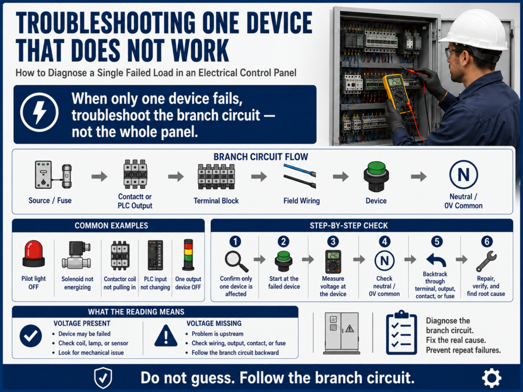
When troubleshooting an electrical control panel, not every problem means the whole system is down. Sometimes the panel has power, the PLC is running, the HMI is working, and most devices operate normally — but one device does not work.
Examples:
One pilot light does not turn on.
One relay does not energize.
One solenoid valve does not actuate.
One contactor coil does not pull in.
One sensor input does not change state.
One PLC output device does not energize.
This type of problem requires a focused troubleshooting method.
When only one device fails, do not start at the main disconnect or replace random parts. Instead, focus on the specific branch circuit for that device.
Control circuits are generally designed so that an individual circuit controls one function of a machine or process, such as starting a motor, stopping a motor, controlling a solenoid valve, or responding to a limit switch or proximity switch.
1. First Question: Is It One Device or a System Problem?
Before testing, determine the scope of the failure.
Ask:
Is only this device not working?
Are similar devices working?
Is control power available?
Is the PLC running?
Are other outputs energizing?
Are other lights, relays, or solenoids working?
This matters because the troubleshooting path changes depending on the answer.
| Condition | Troubleshooting Direction |
|---|---|
| Nothing works | Start at incoming power or control power |
| One section is down | Check common power for that section |
| One device is down | Troubleshoot that device branch circuit |
| PLC output LED is ON but device is OFF | Check output power, field wiring, and load |
| Device works manually but not automatically | Check logic, permissives, commands, and interlocks |
A strong technician always defines the size of the problem first.
2. Use the Branch Circuit Method
When one device fails, isolate the branch circuit.
A branch circuit is the part of the control circuit dedicated to that device.
Example:
L1 → Fuse → Relay Contact → Pilot Light → NeutralOr for a solenoid:
+24VDC → PLC Output → Terminal Block → Solenoid Coil → 0VDCOr for a contactor coil:
L1 → Stop PB → Start PB → Overload Contact → M1 Coil → NeutralThe goal is to prove where the expected voltage or signal disappears inside that specific branch.
3. Start at the Failed Device
The best place to start is usually the device that is not working.
Example:
Pilot light does not turn on.Start by checking the pilot light circuit.
Example:
Solenoid valve does not energize.Start by checking voltage at the solenoid coil.
Example:
Contactor does not pull in.Start by checking voltage across the contactor coil.
This follows the backtracking method:
Failed Device → Field Wiring → Terminal Block → Control Contact / PLC Output → Fuse / SourceThe manual emphasizes using the circuit diagram as a guide and beginning troubleshooting from the point of failure, then working backward toward the source.
4. Check Voltage at the Device
The first major test is:
Is the device receiving the correct voltage when it is supposed to operate?Examples:
| Device | Expected Test |
|---|---|
| 120 VAC pilot light | Measure across the lamp terminals |
| 24 VDC solenoid | Measure +24VDC to 0VDC at the coil |
| Contactor coil | Measure across A1 and A2 |
| Relay coil | Measure across coil terminals |
| PLC input sensor | Measure sensor output to 0VDC |
| PLC output load | Measure at output terminal and field device |
Result interpretation:
| Reading | Meaning |
|---|---|
| Correct voltage present | Device may be failed |
| No voltage present | Problem is upstream or return path is open |
| Low voltage present | Possible voltage drop, loose connection, overloaded supply |
| Voltage on one side only | Check neutral/common return |
| Voltage present at panel but not at field device | Field wiring or connector issue |
This one test can immediately narrow the problem.
5. Do Not Forget the Return Path
A device needs a complete circuit.
For AC:
L1 → Load → NeutralFor DC:
+24VDC → Load → 0VDCA common mistake is checking only the hot side.
Example:
You measure +24VDC at one side of a solenoid.
The solenoid does not energize.
That does not prove the circuit is complete.
You must also verify:
Is 0VDC common present?
Is the neutral connected?
Is the return wire broken?
Is the terminal loose?
Is the common fuse open?
A missing common or neutral can make one device fail even when power appears to be present.
6. Example 1: One Pilot Light Does Not Turn On
Symptom:
The left pilot light does not work.
The right pilot light works correctly.
The relay responds to the pushbuttons.
This tells us the whole panel is not dead. The problem is likely related to the failed pilot light branch.
Basic circuit:
L1 → Relay Contact → Pilot Light → NeutralTroubleshooting steps:
Step 1 — Operate the circuit
Confirm that the relay or controlling device is actually changing state.
Does the relay energize?
Does another light respond?
Does the control circuit appear active?
If yes, continue with the failed light branch.
Step 2 — Measure across the pilot light
Expected: 120 VAC when the light should be ONIf correct voltage is present:
Suspect bad bulb, LED module, lamp holder, or loose lamp connection.If voltage is missing:
Move backward in the circuit.Step 3 — Measure before the pilot light
Measure hot side of the pilot light to neutral.
Expected: 120 VAC when commanded.
If hot side is present, check neutral.
If hot side is missing, move backward toward the relay contact.
Step 4 — Check before and after the relay contact
Before relay contact: should have source voltage.
After relay contact: should have voltage when relay is energized.
If voltage is present before the contact but not after it, the contact may not be closing.
The manual gives a similar example in Basic Controls Problem 2, where one light is not operating. The procedure checks whether the other light and relay respond, then measures voltage at the failed light and works backward toward the relay contact and wiring.
7. Example 2: One Solenoid Valve Does Not Energize
Symptom:
One pneumatic valve does not actuate.
Other valves on the machine work.
PLC output LED turns ON.
Possible causes:
Bad solenoid coil
Missing 24 VDC at valve
Open 0VDC common
Broken field cable
Bad connector
Blown output fuse
Bad PLC output channel
Loose terminal block
Wrong output command
Mechanical/pneumatic valve issue
Basic circuit:
PLC Output → Terminal Block → Field Cable → Solenoid Coil → 0VDC CommonTroubleshooting steps:
Step 1 — Check PLC output status
Is the output LED ON?
Is the PLC logic commanding the output?
If the output is not commanded, the issue may be logic-related.
If the output is commanded, continue with electrical testing.
Step 2 — Measure voltage at the solenoid coil
Expected: approximately 24 VDC when commanded.If 24 VDC is present and the valve does not actuate:
Possible bad solenoid coil or valve mechanical issue.If 24 VDC is missing:
Move backward toward terminal block and PLC output.Step 3 — Measure at the terminal block
Panel side: Is 24 VDC leaving the panel?
Field side: Is 24 VDC going out to the cable?
If voltage exists at the panel but not at the valve, suspect field wiring, connector, or junction box.
Step 4 — Check the common
Verify 0VDC common at the solenoid.If +24VDC is present but 0VDC is missing, the solenoid will not energize.
8. Example 3: One Contactor Does Not Pull In
Symptom:
Motor M1 does not start.
Other motors work.
Control power is available.
M1 contactor does not pull in.
Basic control circuit:
L1 → Stop PB NC → Start PB NO → Overload NC → M1 Coil → NeutralTroubleshooting steps:
Step 1 — Measure across the contactor coil
Expected: coil-rated voltage when Start is pressed or command is active.If voltage is present:
Possible failed coil, wrong coil voltage, loose coil terminal, or mechanical contactor issue.If voltage is not present:
Move backward through the overload, start command, stop circuit, fuse, and source.Step 2 — Check overload auxiliary contact
Is the overload tripped?
Is the NC overload contact closed?
Is voltage present after the overload contact?
Step 3 — Check the start command
Does the Start PB close?
Does the PLC output or relay contact close?
Is the command reaching the coil circuit?
Step 4 — Check neutral
Is A2 connected to neutral or common?
Is the return path open?
A contactor coil cannot energize without both voltage supply and return path.
9. Example 4: PLC Input Does Not Turn ON
Sometimes the failed “device” is not an output. It may be an input signal.
Symptom:
A photo eye detects a box, but the PLC input does not turn ON.Possible causes:
Sensor not powered
Sensor misaligned
Wrong sensor type
Broken wire
Bad connector
Input common missing
Wrong input terminal
PLC input card issue
Sensor output failed
Troubleshooting steps:
Step 1 — Check sensor power
Measure +24VDC and 0VDC at the sensor.Step 2 — Check sensor output
Measure sensor output to 0 VDC while actuating the sensor.Expected:
Output should change state when the target is present.Step 3 — Check signal at panel terminal
Does the signal arrive at the terminal block?Step 4 — Check PLC input LED
Does the input LED turn ON?If the signal reaches the PLC terminal but the input LED does not change, suspect input wiring, common, configuration, or input module issue.
10. Device Receives Voltage but Still Does Not Work
If the correct voltage is present across the device and it still does not work, now the device becomes suspicious.
Possible examples:
| Device | Possible Fault |
|---|---|
| Pilot light | Burned lamp, failed LED module, bad holder |
| Relay | Open coil, stuck mechanism |
| Contactor | Failed coil, mechanical jam, wrong coil voltage |
| Solenoid | Open coil, stuck valve, pneumatic issue |
| Sensor | Failed electronics, misalignment, wrong mode |
| Motor | Open winding, overload issue, mechanical jam |
But do not stop at “bad device.”
Ask:
Why did this device fail?Possible root causes:
Overvoltage
Water intrusion
Heat
Vibration
Wrong voltage rating
Loose terminal
Shorted field cable
Excessive load
Contamination
Mechanical binding
The manual warns that replacing the failed component may be only a quick fix if the root cause is not identified.
11. Device Does Not Receive Voltage
If the device does not receive voltage, the device may not be the problem.
Now move backward.
Typical path:
Device → Field Wiring → Terminal Block → Fuse → Contact / Output → SourceLook for:
Open relay contact
Blown fuse
Loose terminal
Broken wire
Bad connector
Failed PLC output
Missing output common
Open permissive
Open overload contact
Safety circuit not reset
The key question is:
Where is voltage present, and where does it disappear?That point tells you where the fault is located.
12. Troubleshooting Table
| Symptom | First Test | If Voltage Is Present | If Voltage Is Missing |
|---|---|---|---|
| Pilot light OFF | Measure across lamp | Check lamp/holder | Check relay contact/wiring |
| Solenoid OFF | Measure at solenoid coil | Check coil/valve | Check terminal/output/common |
| Contactor not pulling in | Measure across coil | Check coil/contactor | Check overload/start/stop/source |
| PLC input not ON | Measure sensor output | Check PLC input/common | Check sensor power/output |
| Relay not energizing | Measure across coil | Check relay coil | Check command/contact/source |
| One output dead | Measure output terminal | Check field wiring/load | Check output fuse/common/module |
13. Practical Technician Report Example
Symptom:
Solenoid valve SV-204 did not energize during automatic cycle.

Expected Operation:
PLC output O:2/4 should energize SV-204 with 24 VDC when the discharge command is active.

Observation:
Other solenoids operated normally. PLC was in Run mode. Output LED O:2/4 turned ON when commanded.

Testing:
Measured 0 VDC at SV-204 coil.
Measured 24 VDC at panel terminal TB3-18.
Measured 0 VDC at field connector near valve.
Verified cable continuity after LOTO.

Finding:
Open conductor in field cable between panel and solenoid connector.

Correction:
Replaced damaged cable and secured it away from machine movement.

Root Cause:
Cable jacket was rubbing against a moving bracket, eventually opening the conductor.

Final Verification:
SV-204 energized correctly in manual mode and automatic cycle.
This type of documentation proves the diagnosis and captures the root cause.
14. Final Checklist
[ ] Confirm only one device is affected.
[ ] Identify the exact device or signal that failed.
[ ] Review the electrical diagram.
[ ] Identify the device voltage and return path.
[ ] Measure voltage at the failed device.
[ ] Check both source side and return/common side.
[ ] If voltage is present, inspect the device.
[ ] If voltage is missing, backtrack through the branch circuit.
[ ] Check terminal blocks and connectors.
[ ] Check fuses, contacts, PLC output, or relay output.
[ ] Verify the command or logic is actually active.
[ ] Repair safely using LOTO when required.
[ ] Verify operation after repair.
[ ] Identify and correct the root cause.
[ ] Document findings.
Final Thoughts
When one device does not work, troubleshoot the branch — not the whole panel.
The rest of the system gives you important information. If other devices are working, the main source is probably good. That allows you to focus on the failed device, its wiring, its control contact, its output channel, its fuse, and its return path.
The professional method is simple:
Confirm the symptom.
Start at the failed device.
Measure expected voltage.
Check the return path.
Backtrack one step at a time.
Find where the signal disappears.
Repair safely.
Verify.
Find root cause.
A good technician does not guess.
A good technician follows the circuit.
In the next post, we will cover:
Motor Starter Troubleshooting Basics
We will look at contactors, overloads, coils, auxiliary contacts, power circuits, control circuits, and how to diagnose why a motor starter does not operate correctly.