19. PLC Forcing: When to Use It and When Not To
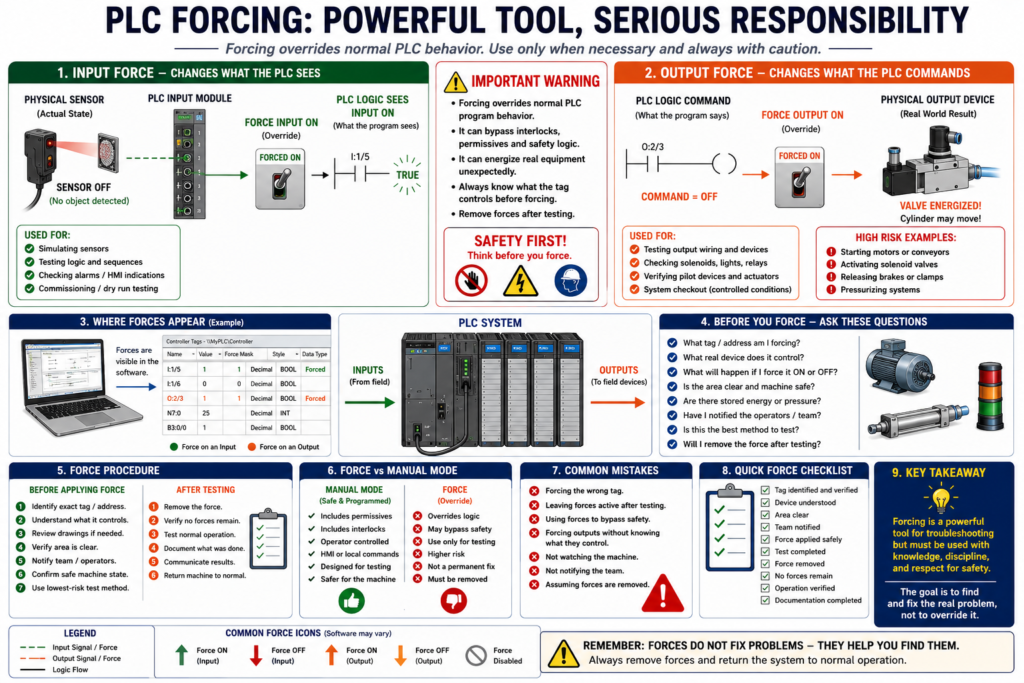
In PLC troubleshooting, one of the most powerful and dangerous tools is forcing.
A PLC force allows a technician or programmer to manually override the normal state of an input or output.
Forcing can be useful during testing, commissioning, troubleshooting, and simulation.
But forcing can also create serious safety risks if it is used incorrectly.
A simple way to understand it is:
Forcing overrides normal PLC behavior.That means the PLC may act differently from what the real machine conditions are actually saying.
According to Programmable Logic Controllers, 6th Edition, forcing external I/O addresses is part of PLC program control and troubleshooting practices. The book also places forcing in the same chapter area as commissioning, monitoring, troubleshooting, and safety-related topics, which is important because forcing must always be treated as a controlled troubleshooting action.
What Is PLC Forcing?
A force is a manual override applied to a PLC input or output point.
For example:
Force an input ON
Force an input OFF
Force an output ON
Force an output OFF
When a force is active, the PLC does not behave only according to the real-world device or normal program logic.
Instead, the forced condition overrides the normal state.
Why Forces Are Used
Forces may be used for:
Testing inputs
Testing outputs
Simulating field devices
Commissioning new machines
Checking wiring
Testing alarms
Testing HMI indicators
Verifying output devices
Troubleshooting a suspected bad sensor
Troubleshooting a suspected bad output module
Forcing is not automatically wrong.
The problem is using forces without understanding what they affect.
Input Force vs Output Force
There is a big difference between forcing an input and forcing an output.
This is one of the most important safety concepts.
Input Force
An input force changes what the PLC program sees.
Example:
Physical sensor is OFF
Input force makes the PLC logic see it as ON
The actual field device may still be OFF, but the PLC logic believes the input is ON.
Example:
Door_Closed_LS physical input = OFF
Door_Closed_LS forced ON
PLC logic believes door is closed
This can be useful for testing logic, but it can also be dangerous if the input represents a safety or permissive condition.
Output Force
An output force changes what the PLC commands to the real-world output.
Example:
PLC logic says output should be OFF
Output force turns physical output ON
This is usually more dangerous than an input force because it can energize real equipment.
An output force can activate:
Motor starter
Solenoid valve
Hydraulic valve
Pneumatic cylinder
Heater
Pump
VFD run command
Alarm horn
Reject air blast
Actuator
Before forcing an output, always think:
What will move, energize, open, close, start, heat, release, or pressurize?
Simple Comparison
| Type of Force | What It Affects | Main Risk |
|---|---|---|
| Input Force | What the PLC logic sees | PLC may believe a false condition |
| Output Force | What the PLC commands physically | Equipment may energize or move |
| Internal Bit Force | Internal program condition | Logic may behave differently than expected |
| HMI Command Force | Operator command simulation | Machine may respond unexpectedly |
Example 1: Input Force
Situation
A machine will not start because the PLC does not see the Box_Present photoeye.
The sensor is being replaced, but you want to test the logic.
You force:
DI_Box_Present = ONThe PLC now believes a box is present.
This can help test:
HMI indication
Sequence logic
Permissive logic
Counter logic
Alarm logic
But the real box may not actually be there.
That is why the technician must understand the process before forcing.
Example 2: Output Force
Situation
A solenoid valve does not energize.
You want to test if the valve coil and wiring are good.
You force:
DO_Valve_Open = ONPossible result:
Valve energizes
Cylinder moves
Air pressure shifts
Machine part changes position
This could be useful, but it can also be dangerous if someone is near the equipment.
Before doing this, verify:
Air pressure status
Mechanical position
Personnel safety
Machine mode
Stored energy
Interlocks
Area clearance
Authorization
The Golden Rule of Forcing
Use this rule:
Never force anything unless you know exactly what it controls.Do not force based only on the tag name.
A tag name may be wrong, unclear, reused, or poorly documented.
Verify the actual field device.
Why Forcing Can Be Dangerous
Forcing can bypass normal program behavior.
It may bypass:
Interlocks
Permissives
Fault logic
Sequence logic
Operator commands
Sensor feedback
Machine status checks
Normal output commands
Example:
PLC logic says motor should be OFF because guard door is open.
Technician forces motor output ON.
Motor starts even though the logic would normally block it.
That is the danger.
The force can override the logic that was designed to protect the machine or process.
Important Safety Note
Forcing must never be used as a shortcut to bypass safety.
Do not use forces to bypass:
Emergency stops
Safety gates
Light curtains
Safety relays
Safety PLC logic
Guard door circuits
Personnel protection devices
Lockout/tagout requirements
Safety circuits exist to protect people.
Forcing is a troubleshooting tool, not a safety bypass method.
When It May Be Appropriate to Force
Forcing may be appropriate when:
The machine is under controlled testing
The area is clear
The device being forced is identified
The risk is understood
The correct personnel are aware
The action is temporary
The force is documented
The force will be removed immediately after testing
Good examples:
Testing a pilot light output
Testing an HMI indication
Simulating a product sensor during dry-run testing
Checking an alarm bit during commissioning
Testing a relay output with equipment isolated
When You Should Not Force
Do not force when:
You are not sure what the tag controls
People are near moving equipment
The output may start a motor unexpectedly
The force could energize air or hydraulic motion
The force bypasses a safety device
You cannot see the machine
You cannot remove the force afterward
You are using it as a permanent fix
The root cause is unknown and risk is high
A force should never become a “temporary permanent fix.”
If a machine only works because a force is active, the problem is not solved.
Input Force Example: Good Use
Testing an HMI Display
You want to verify that an HMI indicator changes color when a sensor is ON.
You force:
DI_Level_High = ONThen check:
Does HMI show High Level?
Does alarm banner appear?
Does indicator change color?
Does the correct message display?
This can be acceptable during controlled testing because you are testing display logic, not physically energizing a machine output.
Still, it must be removed after testing.
Output Force Example: Risky Use
Forcing a Conveyor Motor
You force:
DO_Conveyor_Run = ONPossible result:
Motor starts
Belt moves
Product moves
Mechanical jam worsens
Operator is surprised
Downstream equipment receives product unexpectedly
This should only be done under controlled conditions.
Better practice:
Use manual/jog mode if available
Verify interlocks
Notify operators
Clear the area
Use local disconnect/control if required
Forcing vs Manual Mode
Forcing is not the same as proper manual mode.
Manual Mode
Manual mode is programmed and controlled.
It usually includes:
Permissives
Interlocks
Operator commands
HMI control
Fault checks
Safe operating limits
Feedback monitoring
Force
A force is an override.
It may ignore normal program structure.
Simple rule:
Use manual mode when possible.
Use forcing only when necessary and controlled.
Forcing vs Bypass
Forcing and bypassing are related, but not exactly the same.
Force
A force overrides a PLC point or value.
Example:
Force input ON
Force output OFF
Bypass
A bypass is usually a logic condition that intentionally ignores a device, alarm, or permissive.
Example:
Bypass low level switch
Bypass door sensor
Bypass photoeye
Both must be controlled.
Both must be documented.
Both can be dangerous if misused.
What Happens If You Forget a Force?
Forgetting an active force is a serious problem.
It can cause:
Wrong troubleshooting conclusions
Unexpected machine behavior
False HMI status
Alarms not working correctly
Outputs staying ON or OFF
Inputs appearing healthy when they are not
Machine starting later unexpectedly
Example:
A sensor input is forced ON.
The real sensor fails.
PLC still sees input ON.
Machine continues operating with false feedback.
That is why forces must be removed immediately after testing.
Force Indicators
Many PLC platforms clearly indicate when forces are installed or enabled.
Depending on the PLC platform, you may see:
Force LED
Software force warning
I/O forced status
Controller status indicator
Online toolbar warning
Force table
For an Automation Technician, this is important:
When troubleshooting strange behavior, always check if forces are active.
Common Troubleshooting Problem: Hidden Force
Problem
A motor keeps running even though the logic says it should be OFF.
Possible Cause
Output is forced ONCheck
Look for active forces in PLC software.
Check controller force indicator.
Check output force table.
Verify whether forces are enabled.
Common Troubleshooting Problem: Input Force
Problem
PLC shows a limit switch ON, but the physical switch is not made.
Possible Cause
Input is forced ONCheck
Check the actual input LED.
Check the PLC tag.
Check force status.
Compare physical input state to forced logic state.
If the input LED is OFF but the PLC logic sees the input ON, a force may be active.
Recommended Force Procedure
Before forcing anything, use a controlled procedure.
Before Applying a Force
1. Identify the exact tag or address.
2. Confirm what physical device it represents.
3. Review the electrical drawing if needed.
4. Understand what will happen when the force is applied.
5. Verify machine area is clear.
6. Notify affected operators or team members.
7. Confirm energy sources and stored energy.
8. Use the lowest-risk test method available.
During the Force
1. Apply only the force needed.
2. Watch the machine response.
3. Monitor the PLC logic.
4. Monitor the field device.
5. Keep communication with the team.
6. Do not walk away from the machine.
After Testing
1. Remove the force.
2. Disable forces if required.
3. Verify no forces remain.
4. Confirm the machine returns to normal logic control.
5. Test normal operation.
6. Document what was done.
7. Communicate results to the team.
Force Documentation
Any force used during troubleshooting should be documented.
Good documentation includes:
Date and time
Machine name
PLC tag or address
Reason for force
Who applied the force
What was tested
Result of the test
Time force was removed
Confirmation that no forces remain
Example note:
Forced DO_Valve_Open momentarily to verify solenoid wiring and coil.
Valve energized correctly.
Force removed after test.
No forces remaining.
Good documentation protects the technician and the team.
Better Alternatives to Forcing
Before forcing, consider safer alternatives:
Use manual mode
Use jog function
Use simulation mode
Use HMI maintenance controls
Use temporary test bit in controlled offline logic
Test output voltage with meter
Disconnect load and test output module
Use PLC monitoring only
Test the field device locally if safe
Forcing should be one option, not the first reflex.
Practical Example: Troubleshooting a Solenoid
Problem
A valve does not open.
Bad Approach
Immediately force the output ON.Better Approach
1. Check if PLC command is ON.
2. Check output LED.
3. Check field power.
4. Check fuse.
5. Measure voltage at output terminal.
6. Measure voltage at solenoid coil.
7. Verify common.
8. Check coil resistance.
9. Confirm valve is not mechanically stuck.
10. Force output only if needed and safe.
This is a professional troubleshooting path.
Practical Example: Testing a Photoeye Input
Problem
PLC does not see a photoeye.
Good Troubleshooting Path
1. Check photoeye power.
2. Check alignment.
3. Check sensor LED.
4. Measure signal wire.
5. Verify PLC input terminal voltage.
6. Check PLC input LED.
7. Check input tag online.
8. Check for active forces.
If needed, you may force the input ON to test downstream logic, but do not confuse that with fixing the real sensor problem.
Automation Technician Notes
For an Automation Technician, the key point is:
A force is a diagnostic tool, not a repair.
A force can help prove whether logic, wiring, or devices respond correctly.
But it does not fix:
Bad sensors
Broken wires
Failed relays
Faulted VFDs
Mechanical jams
Incorrect scaling
Bad feedback
Wrong module configuration
Always remove forces after testing and continue troubleshooting the real root cause.
Force Risk Levels
| Force Type | Risk Level | Comment |
|---|---|---|
| HMI display bit | Low to medium | Usually safer if it does not command motion |
| Internal diagnostic bit | Medium | Can affect logic depending on use |
| Input permissive | Medium to high | PLC may believe a false condition |
| Output pilot light | Low to medium | Usually low risk but still verify |
| Solenoid valve output | High | Can move pneumatic/hydraulic devices |
| Motor/VFD run output | High | Can start motion |
| Safety-related input/output | Very high | Do not bypass safety casually |
Common Mistakes with PLC Forcing
1. Forcing the Wrong Tag
A similar tag name can cause mistakes.
Example:
DO_Conveyor1_Run
DO_Conveyor2_Run
Always verify the exact tag.
2. Forgetting to Remove the Force
This is one of the biggest mistakes.
Always check for remaining forces before leaving.
3. Using Force as a Permanent Fix
A force should not be left active to keep production running without proper review and authorization.
4. Forcing Without Watching the Machine
Never force an output if you cannot see or control the machine response.
5. Not Telling the Team
Operators and other technicians must know when the machine is under forced testing.
Force Checklist for the Field
Use this quick checklist:
Before:
- Identify exact tag/address
- Know what device it controls
- Verify area is clear
- Notify team
- Confirm safe machine state

During:
- Apply only necessary force
- Monitor machine response
- Stay with equipment
- Keep communication

After:
- Remove force
- Verify no forces remain
- Test normal operation
- Document results
Key Terms
| Term | Meaning |
|---|---|
| Force | Manual override of a PLC input or output |
| Input Force | Makes PLC logic see an input as ON or OFF |
| Output Force | Commands an output ON or OFF regardless of normal logic |
| Forced ON | PLC treats point as ON |
| Forced OFF | PLC treats point as OFF |
| Force Enabled | Controller is allowing active forces to affect logic |
| Force Installed | A force exists on an I/O point |
| Manual Mode | Programmed operator control mode |
| Bypass | Logic condition used to ignore or override a device/permissive |
| Permissive | Condition required before action is allowed |
| Interlock | Condition that prevents unsafe or unwanted action |
| Output Mapping | Final logic section where commands are assigned to physical outputs |
Final Thoughts
PLC forcing is a powerful troubleshooting tool, but it must be used with discipline.
An input force changes what the PLC logic sees.
An output force can energize real-world devices.
That difference matters.
Forcing should only be used when the technician understands the device, the machine state, the risk, and the expected result.
The professional rule is simple:
Force only when necessary.
Force only when safe.
Remove the force immediately after testing.
Document what was done.
Used correctly, forcing can help diagnose PLC systems faster.
Used carelessly, it can create unsafe machine behavior and serious troubleshooting confusion.