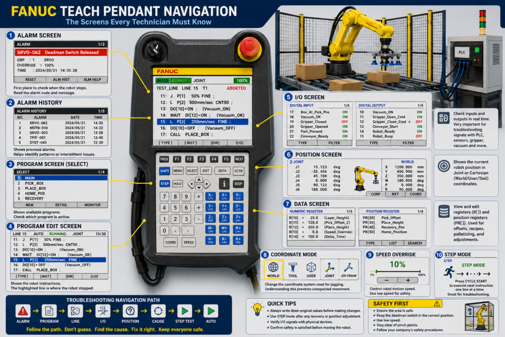
2. FANUC Teach Pendant Navigation: The Screens Every Technician Must Know
Introduction
Once you understand what the FANUC Teach Pendant is, the next step is learning how to navigate the most important screens.
For an automation technician, the goal is not to memorize every menu on day one. The goal is to know where to go when the robot stops, how to find useful information, and how to avoid changing something by mistake.
In a real production environment, the pendant helps you answer these questions:
Why did the robot stop?
What program was running?
What line stopped?
Is the robot waiting for a signal?
Is the problem related to safety, I/O, motion, gripper, PLC, or product position?
This post focuses on the main Teach Pendant screens that every technician should know.
1. The Technician Navigation Mindset
When a robot is down, do not start pressing buttons randomly.
Use this sequence:
Alarm → Program → Line → I/O → Position → Jog → Step Test → AutoThis sequence gives you control of the situation.
| Step | Purpose |
|---|---|
| Alarm | Find why the robot stopped |
| Program | Find what routine was running |
| Line | Find the exact instruction where it stopped |
| I/O | Check signals from sensors, PLC, gripper, and safety |
| Position | Check where the robot is physically located |
| Jog | Move the robot manually if needed |
| Step Test | Test one instruction at a time |
| Auto | Return to production only after safe verification |
2. Alarm Screen
The Alarm Screen is the first place to check when the robot stops.
What to look for
When you open the alarm screen, identify:
Alarm code
Alarm message
Alarm type
Active or historical alarm
Time of alarm
Whether it returns after RESET
Common alarm families
| Alarm Type | General Meaning |
|---|---|
| SRVO | Servo, motor, axis, brake, safety, or motion-related issue |
| MOTN | Motion not allowed or motion error |
| INTP | Program execution or interpreter issue |
| SYST | System-level issue |
| TPIF | Teach Pendant or interface issue |
| Collision Guard | Robot detected abnormal force |
| Overtravel | Axis moved beyond allowed limit |
| Safety | E-stop, gate, fence, scanner, or enabling device issue |
Important rule
Do not treat the RESET button as the solution.
RESET only clears the alarm if the real condition is corrected.
Example:
Alarm: Fence OpenPressing RESET will not solve the issue if the safety gate is still open or the interlock is not satisfied.
3. Program Select Screen
The Program Select Screen shows the available robot programs.
This is where you usually find programs such as:
MAIN
HOME
PICK
PLACE
PALLET
RECOVERY
GRIPPER_OPEN
GRIPPER_CLOSE
AUTO_START
What technicians should look for
| Item | Why It Matters |
|---|---|
| Active program | Shows what the robot was running |
| Main routine | Usually controls the overall cycle |
| Subprograms | Smaller routines called by the main program |
| Recovery program | Used to recover the robot safely |
| Home program | Sends robot to a known safe position |
| Program comments | Help identify the purpose of each routine |
Practical example
You may see:
MAIN
PICK_BOX
PLACE_BOX
HOME_POS
RECOVERY
If the robot stopped while handling a box, the active program may be PICK_BOX or PLACE_BOX, but the main sequence may be controlled by MAIN.
That is why it is important to know not only the selected program, but also the current line where execution stopped.
4. Program Edit Screen
The Program Edit Screen shows the actual robot instructions.
This is one of the most important screens for troubleshooting.
Example:
1: UFRAME_NUM=1 ;
2: UTOOL_NUM=2 ;
3: J P[1] 50% FINE ;
4: L P[2] 500mm/sec CNT50 ;
5: DO[10]=ON ;
6: WAIT DI[12]=ON ;
7: L P[3] 250mm/sec FINE ;
8: DO[10]=OFF ;
How to read this
| Instruction | Meaning |
|---|---|
UFRAME_NUM=1 | User Frame 1 is active |
UTOOL_NUM=2 | Tool Frame 2 is active |
J P[1] | Joint move to position P[1] |
L P[2] | Linear move to position P[2] |
DO[10]=ON | Turn ON digital output 10 |
WAIT DI[12]=ON | Wait until digital input 12 turns ON |
FINE | Stop exactly at the point |
CNT50 | Blend through the point smoothly |
Technician focus
When troubleshooting, look for:
WAIT DI[x]
WAIT R[x]
DO[x]=ON/OFF
CALL program_name
J P[x]
L P[x]
IF condition
LBL/JMP
A robot stopped on a WAIT DI[x]=ON line is often waiting for a real-world condition.
That condition may come from:
- PLC
- Sensor
- Gripper
- Vacuum switch
- Conveyor
- Safety system
- Product detection
- Pneumatic device
5. Current Line Number
The current line number is critical.
It tells you exactly where the robot stopped.
Example
Robot stopped here:
15: WAIT DI[25]=ON ;DI[25] is labeled:
Gripper_ClosedThis means the robot is waiting for confirmation that the gripper closed.
Possible causes:
| Possible Cause | What to Check |
|---|---|
| Gripper did not close | Check air, cylinder, solenoid |
| Sensor not made | Check proximity/reed switch |
| Product misaligned | Check box/container position |
| Output not energizing | Check robot DO to solenoid |
| Air pressure low | Check regulator and supply |
| Cable issue | Check sensor wiring |
| PLC condition missing | Check PLC permissive if signal comes from PLC |
This is why the current line is so powerful. It tells you what the robot expected to happen.
6. I/O Screen
The I/O Screen is where technicians solve many robot problems.
Robots communicate with:
- PLC
- Sensors
- Gripper
- Vacuum system
- Conveyors
- Safety devices
- Machine modules
Common robot inputs
| Input Signal | Meaning |
|---|---|
| Part Present | Product is ready |
| Box In Position | Box is located correctly |
| Gripper Opened | Gripper open sensor is ON |
| Gripper Closed | Gripper closed sensor is ON |
| Vacuum OK | Vacuum level is acceptable |
| Conveyor Ready | Conveyor is ready |
| Safe To Pick | PLC permits robot to enter |
| Safe To Place | PLC permits robot to place |
| Cell Ready | Cell conditions are satisfied |
| Fault Reset Request | Reset request from PLC or HMI |
Common robot outputs
| Output Signal | Meaning |
|---|---|
| Robot Ready | Robot is ready |
| Robot Running | Robot is executing |
| Robot Faulted | Robot has an alarm |
| Robot Home | Robot is at home position |
| Robot Busy | Robot is in cycle |
| Pick Complete | Pick sequence completed |
| Place Complete | Place sequence completed |
| Gripper Open Cmd | Command to open gripper |
| Gripper Close Cmd | Command to close gripper |
| Vacuum On Cmd | Command to turn vacuum ON |
Practical I/O troubleshooting method
When the robot is waiting for a signal:
1. Identify the DI number.
2. Read the DI comment/name.
3. Check if the signal is ON or OFF.
4. Check the physical device.
5. Check the PLC input/output if applicable.
6. Check the robot I/O mapping.
7. Check wiring, air, sensor, or mechanical condition.
Example:
WAIT DI[30]=ON
DI[30] = Box_At_Pick_Position
If DI[30] is OFF:
- Check photo eye.
- Check box position.
- Check sensor LED.
- Check conveyor indexing.
- Check PLC logic.
- Check cable or input module.
- Check if the robot is looking at the correct signal.
7. Position Screen
The Position Screen shows where the robot is.
You may see the robot position in different formats:
Cartesian position
X = 1200.000
Y = 450.000
Z = 350.000
W = 180.000
P = 0.000
R = 90.000
Joint position
J1 = 15.000
J2 = -35.000
J3 = 45.000
J4 = 0.000
J5 = 90.000
J6 = 180.000
Cartesian vs Joint
| Type | Use |
|---|---|
| Cartesian | Useful for X/Y/Z position adjustment |
| Joint | Useful for seeing robot axis angles |
| Cartesian Z | Often used for height adjustment |
| Joint J1-J6 | Useful for manual recovery and avoiding awkward posture |
For pick-and-place applications, Cartesian position is especially important because height changes are usually made in the Z direction, depending on the active frame.
8. DATA Screen
The DATA Screen is where you can find registers and position registers.
This is important because many robot programs do not use only fixed positions.
They may use:
R[x]    Numeric Register
PR[x]   Position Register
P[x]    Program Position
Registers
Numeric registers store numbers.
Example:
R[10] = 25.0This could represent:
- Stack height
- Layer number
- Product count
- Offset distance
- Recipe value
- Speed value
- Delay time
Position Registers
Position registers store position data.
Example:
PR[20] = Pick_Offset
PR[30] = Place_Height
PR[40] = Recovery_Position
Position registers are commonly used for:
- Offsets
- Palletizing
- Recipe adjustment
- Height adjustment
- Calculated positions
- Shared positions between programs
Important technician rule
Before changing anything in DATA, write down the original value.
Example:
Before:
PR[30] Place_Height
X = 1000.000
Y = 500.000
Z = 350.000
W = 180.000
P = 0.000
R = 90.000
If you change Z from 350.000 to 360.000, document it.
After:
Z = 360.000
This allows you to return to the original value if needed.
9. Coordinate Screen / COORD Button
The coordinate system determines how the robot moves when jogging.
This is one of the most important concepts for beginners.
Common coordinate systems
| Coordinate Mode | Description |
|---|---|
| Joint | Moves one robot axis at a time |
| World | Moves relative to the robot/world coordinate system |
| Tool | Moves relative to the tool orientation |
| User | Moves relative to the user-defined work area |
| Jog Frame | Custom jogging coordinate system, if configured |
Practical meaning
If you press +Z, what happens?
It depends on the active coordinate system.
| Mode | What +Z May Do |
|---|---|
| World | Move upward relative to world |
| User | Move upward relative to the user frame |
| Tool | Move along the tool’s Z direction |
| Joint | Not applicable as X/Y/Z; moves selected joint |
For height changes, technicians usually need to understand whether the robot is using World, User, or Tool.
In many pick-and-place applications:
Z+ = move up
Z- = move down
But this depends on the frame setup. Always verify with small movements at low speed.
10. Speed Override Screen / Button
The speed override controls how fast the robot moves.
When troubleshooting, recovering, or teaching positions, use low speed.
Recommended for beginners:
5% to 10%Use higher speed only when you are confident and the path is clear.
Never move fast near:
- Conveyor
- Box
- Container
- Pallet
- Gripper
- Safety fence
- Machine frame
- Sensors
- Air lines
- Other equipment
Speed override is one of the easiest ways to reduce risk during recovery.
11. Step Mode
STEP mode lets you execute the program one instruction at a time.
This is very useful after:
- Alarm recovery
- Position adjustment
- Robot crash
- Product jam
- Bad pick
- Bad place
- Gripper issue
- Program change
Example
Instead of running the full program in AUTO, you can step through:
1. Move to approach position
2. Open gripper
3. Move to pick position
4. Close gripper
5. Wait for gripper closed
6. Move up
7. Move to place position
8. Open gripper
9. Wait for gripper opened
10. Return home
This makes troubleshooting more controlled.
12. Screens You Should Avoid Changing at First
Not every screen is safe for beginners.
Avoid changing these unless you are trained, authorized, and have a backup:
| Area | Why Be Careful |
|---|---|
| System Variables | Can affect robot behavior globally |
| Mastering Data | Incorrect values can cause position errors |
| Frames | Changes affect many positions |
| Tool Data | Affects robot path and orientation |
| Payload Data | Affects motion performance and collision detection |
| I/O Mapping | Can break robot/PLC communication |
| Safety Configuration | Can create serious hazards |
| UOP Configuration | Can affect AUTO operation |
| Program Select Setup | Can affect production start sequence |
You can view many of these areas for troubleshooting, but do not modify them casually.
13. Real Plant Example: Robot Stopped After Picking a Box
Symptom
The robot picks a box, moves up slightly, then stops.
Pendant shows
WAIT DI[18]=ONDI[18] comment:
Vacuum_OKInterpretation
The robot is waiting for confirmation that vacuum is strong enough.
Possible causes
| Cause | Check |
|---|---|
| Vacuum cup damaged | Inspect cups |
| Air supply low | Check regulator |
| Product surface leaking | Check box/container condition |
| Vacuum sensor not adjusted | Check sensor threshold |
| Solenoid not activating | Check DO command |
| Hose leaking | Inspect tubing |
| Filter clogged | Check vacuum generator/filter |
| Product not centered | Check pick position |
Technician action
1. Check DI[18] on the I/O screen.
2. Check if Vacuum_ON output is active.
3. Check physical vacuum device.
4. Check sensor LED.
5. Check air pressure.
6. Check gripper contact with product.
7. Correct the issue.
8. Reset alarm if needed.
9. Test in STEP mode.
This is a good example of using pendant navigation to find the real cause.
14. Basic Navigation Checklist
Use this checklist every time you approach a stopped robot.
1. Check that the area is safe.
2. Read the alarm screen.
3. Write down the alarm code.
4. Find the active program.
5. Find the current line.
6. Identify if the robot stopped on WAIT, motion, CALL, or I/O.
7. Check relevant inputs and outputs.
8. Check robot position.
9. Verify product, gripper, air, and sensors.
10. Correct the real cause.
11. Reset only after correction.
12. Jog slowly if recovery is needed.
13. Run in STEP mode before AUTO.
14. Return to AUTO only after safe verification.
15. What to Practice This Week
For this lesson, practice navigation only. Do not modify positions yet.
Practice tasks
1. Open the alarm screen.
2. Open the program list.
3. Open the active program.
4. Find the current line.
5. Open the I/O screen.
6. Search for a DI signal.
7. Search for a DO signal.
8. Open the position screen.
9. Change between Joint, World, Tool, and User jog mode.
10. Lower the speed override.
11. Enable STEP mode.
12. Observe the robot sequence one line at a time.
The goal is to build confidence without making unsafe changes.
Conclusion
The Teach Pendant becomes much easier when you know which screens matter first.
For a technician, the most important screens are:
Alarm Screen
Program Screen
Current Line
I/O Screen
Position Screen
Data Screen
Coordinate Mode
Speed Override
Step Mode
When the robot stops, use a structured troubleshooting path:
Alarm → Program → Line → I/O → Position → Cause → Reset → Step Test → AutoThis method helps you avoid guessing and helps you troubleshoot like a professional automation technician.