3. Pneumatic Directional Control Valves Explained: 3/2, 5/2, and 5/3 Valves
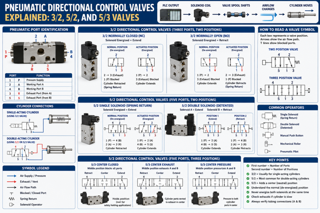
Introduction
Directional control valves are among the most important components in an industrial pneumatic system.
The compressed-air supply provides energy, but the directional valve determines where that air goes.
By changing the airflow path, the valve can:
- Extend a pneumatic cylinder
- Retract a pneumatic cylinder
- Stop cylinder movement
- Vent trapped air
- Hold an actuator in position
- Return a mechanism to a safe state
In PLC-controlled machines, the directional valve creates the physical connection between an electrical output and mechanical motion.
The basic control chain is:
PLC Output → Solenoid Coil → Valve Spool Shifts → Airflow Changes → Cylinder Moves
To troubleshoot pneumatic motion correctly, an Automation Technician must understand:
- Valve port identification
- Number of valve positions
- Normal or de-energized state
- Single-solenoid and double-solenoid operation
- Exhaust paths
- Pneumatic symbols
- Cylinder connections
What Is a Directional Control Valve?
A directional control valve controls the path followed by compressed air.
It does not normally generate air pressure. Instead, it connects or blocks different pneumatic ports.
Depending on its position, the valve may connect:
- Supply pressure to a cylinder port
- A cylinder port to exhaust
- Both cylinder ports to exhaust
- Both cylinder ports to supply
- All ports in a blocked condition
The internal moving component is commonly called a spool.
When the spool changes position, the internal passages inside the valve change.
Solenoid De-Energized
        ↓
Spool in Normal Position
        ↓
One Airflow Path Is Active

Solenoid Energized
        ↓
Spool Shifts
        ↓
A Different Airflow Path Is Active
Understanding Valve Designations
Directional valves are commonly identified using two numbers separated by a slash.
Examples:
- 3/2 valve
- 5/2 valve
- 5/3 valve
The first number represents the number of ports or ways.
The second number represents the number of valve positions.
Example:
5/2 Valve

5 = Five ports
2 = Two operating positions
A 5/3 valve has five ports and three operating positions.
This naming system helps identify the basic function of the valve before inspecting its detailed symbol.
Understanding Pneumatic Valve Ports
Directional valves use standardized port numbers and letters.
Common pneumatic port identification includes:
| Port Number | Letter | Function |
|---|---|---|
| 1 | P | Pressure supply |
| 2 | A | Working port A |
| 4 | B | Working port B |
| 3 | R | Exhaust from working port A |
| 5 | S | Exhaust from working port B |
The exact labels may vary slightly between manufacturers, but the function is generally consistent.
Pressure Port
Port 1 or P receives compressed air from the machine air supply.
FRL Unit
   ↓
Port 1 — Pressure Supply
This is normally the main inlet of the valve.
Working Ports
Ports 2 and 4, commonly labeled A and B, connect to the pneumatic actuator.
For a double-acting cylinder:
- Port A may connect to the cap side
- Port B may connect to the rod side
Which port performs extension depends on the tubing arrangement and valve position.
Technicians should never assume that A always means extend without checking the actual machine circuit.
Exhaust Ports
Ports 3 and 5 release air from the actuator to atmosphere.
Exhaust ports may contain:
- Mufflers
- Silencers
- Flow-control devices
- Exhaust tubing
- Quick-exhaust valves
A blocked exhaust can cause slow or incomplete cylinder movement even when the supply pressure is correct.
Valve Symbols and Operating Positions
A directional valve symbol is divided into boxes.
Each box represents one valve position.
A two-position valve has two boxes.
[ Position 1 ][ Position 2 ]
A three-position valve has three boxes.
[ Position 1 ][ Center Position ][ Position 3 ]
The arrows inside each box show the airflow connections.
Blocked ports are commonly shown with a short line or T-shaped termination.
The valve symbol may also include the operating method:
- Solenoid coil
- Spring return
- Manual push button
- Mechanical roller
- Pneumatic pilot
The Normal Position of a Valve
The normal position is the valve condition when no external operating force is applied.
For a spring-return solenoid valve, this usually means:
- Solenoid is de-energized
- Spring holds the spool in its normal position
The box next to the spring symbol represents the normal position.
This is important because the normal position determines what happens when:
- PLC output turns OFF
- Electrical power is lost
- Wire is disconnected
- Output module fails
- Emergency stop removes control power
The de-energized valve state should support the machine’s intended fail-safe behavior.
3/2 Directional Control Valve
A 3/2 valve has:
- Three ports
- Two positions
Typical ports are:
- Pressure
- Working port
- Exhaust
A 3/2 valve is commonly used to control a single-acting cylinder.
Typical 3/2 Valve Ports
Port 1 — Pressure
Port 2 — Working port
Port 3 — Exhaust
In one position, pressure is connected to the actuator.
In the other position, the actuator is connected to exhaust.
3/2 Normally Closed Valve
In a normally closed 3/2 valve, the pressure supply is blocked in the normal state.
The actuator port is normally connected to exhaust.
When the solenoid energizes:
- Pressure connects to the actuator
- Exhaust is blocked
- The cylinder extends
When the solenoid de-energizes:
- Pressure is blocked
- The actuator connects to exhaust
- The spring inside the cylinder retracts it
Simplified operation:
Output OFF
Pressure Blocked
Cylinder Port → Exhaust
Cylinder Retracted by Spring

Output ON
Pressure → Cylinder Port
Exhaust Blocked
Cylinder Extends
3/2 Normally Open Valve
In a normally open 3/2 valve, pressure is connected to the actuator in the normal state.
When the valve is activated:
- Pressure is blocked
- The actuator is vented to exhaust
Normally open valves may be used when the actuator must remain pressurized without electrical power, depending on the application and safety design.
Common 3/2 Valve Applications
- Single-acting cylinders
- Pneumatic pilot signals
- Air blow-off systems
- Vacuum control
- Small clamps
- Spring-return actuators
- Pneumatic logic circuits
5/2 Directional Control Valve
A 5/2 valve has:
- Five ports
- Two operating positions
It is one of the most common valves used with double-acting pneumatic cylinders.
Typical ports include:
- One pressure port
- Two working ports
- Two exhaust ports
Port 1 — Pressure
Port 2 — Working Port A
Port 4 — Working Port B
Port 3 — Exhaust
Port 5 — Exhaust
How a 5/2 Valve Controls a Cylinder
In the first valve position:
- Pressure connects to one side of the cylinder
- The opposite side connects to exhaust
In the second valve position:
- Pressure connects to the opposite side
- The first side connects to exhaust
Example:
Position 1

Pressure → Cap Side
Rod Side → Exhaust
Cylinder Extends
Position 2

Pressure → Rod Side
Cap Side → Exhaust
Cylinder Retracts
The exact direction depends on how ports A and B are connected to the cylinder.
5/2 Single-Solenoid Spring-Return Valve
A single-solenoid 5/2 valve has:
- One electrical solenoid coil
- One mechanical spring
- Two operating positions
When the solenoid is de-energized, the spring holds the valve in its normal position.
When the solenoid energizes, the spool shifts.
When the solenoid turns OFF, the spring returns the valve.
Example:
PLC Output OFF
        ↓
Spring Position
        ↓
Cylinder Retracts
PLC Output ON
        ↓
Solenoid Energized
        ↓
Valve Shifts
        ↓
Cylinder Extends
A common PLC output tag might be:
DO_Cylinder_Extend
With this arrangement, only one PLC output is required.
Advantages of a Single-Solenoid Valve
- Simple electrical control
- Only one PLC output required
- Predictable de-energized position
- Spring returns the valve after power loss
- Useful when one position is defined as the safe position
Important Consideration
The cylinder may move automatically when power is removed because the spring returns the valve to its normal position.
For example, if the normal position retracts the cylinder, loss of electrical power may cause retraction.
This behavior must be considered during:
- Safety analysis
- Maintenance
- Lockout/tagout
- Machine design
- Fault recovery
5/2 Double-Solenoid Valve
A double-solenoid 5/2 valve has one coil on each side of the valve.
Common coil functions are:
- Solenoid A shifts the valve to one position
- Solenoid B shifts the valve to the opposite position
Example PLC outputs:
DO_Cylinder_Extend
DO_Cylinder_Retract
Many double-solenoid valves are bistable or detented.
This means the valve remains in its last commanded position after the active coil is de-energized.
Typical Operation
Extend Solenoid Pulsed
        ↓
Valve Shifts to Extend Position
        ↓
Cylinder Extends
        ↓
Valve Remains in That Position
Retract Solenoid Pulsed
        ↓
Valve Shifts to Retract Position
        ↓
Cylinder Retracts
        ↓
Valve Remains in That Position
The PLC may only need to pulse the appropriate output long enough to shift the spool.
However, some applications keep the coil energized continuously. The correct method depends on the valve design and machine control strategy.
Critical PLC Interlock for Double-Solenoid Valves
Extend and retract solenoids should normally never be energized at the same time.
The PLC program should include a mutual interlock.
Conceptual logic:
Extend Output =
Extend Command
AND NOT Retract Output
Retract Output =
Retract Command
AND NOT Extend Output
Example tag structure:
DO_Cyl_Extend := Extend_Cmd AND NOT DO_Cyl_Retract;

DO_Cyl_Retract := Retract_Cmd AND NOT DO_Cyl_Extend;
This interlock helps prevent conflicting commands.
A properly designed system should also prevent both commands earlier in the control logic, not only at the physical output rung.
Single-Solenoid vs Double-Solenoid 5/2 Valve
| Characteristic | Single Solenoid | Double Solenoid |
|---|---|---|
| Number of coils | One | Two |
| Return method | Spring return | Opposite solenoid |
| PLC outputs required | One | Two |
| Position after power loss | Returns to normal position | May remain in last position |
| Control complexity | Lower | Higher |
| Mutual output interlock | Usually not required | Required |
| Common application | Defined fail position | Maintain last commanded position |
Neither type is automatically better.
The correct selection depends on:
- Required failure position
- Safety requirements
- PLC control strategy
- Cycle speed
- Machine sequence
- Energy isolation behavior
5/3 Directional Control Valve
A 5/3 valve has:
- Five ports
- Three operating positions
The two outer positions normally control extension and retraction.
The center position determines what happens when neither solenoid is energized.
[ Retract ][ Center ][ Extend ]
The center configuration is one of the most important characteristics of a 5/3 valve.
Common 5/3 Center Configurations
Center Closed
In the center position, all valve ports are blocked.
Conceptually:
Pressure Blocked
Port A Blocked
Port B Blocked
Exhaust Ports Blocked
This configuration may help stop or hold a cylinder temporarily.
However, pneumatic air is compressible, and cylinder seals may leak. Therefore, a center-closed valve should not automatically be considered a precision mechanical holding or safety-locking device.
Applications requiring secure load holding may require:
- Rod locks
- Pilot-operated check valves
- Mechanical brakes
- Safety-rated holding devices
Center Exhaust
In the center position:
- Pressure is blocked
- Both cylinder ports connect to exhaust
The cylinder chambers are depressurized.
Depending on load and mechanical conditions, the cylinder may move freely.
This configuration may be used where the actuator should be depressurized in the neutral position.
Center Pressure
In the center position:
- Pressure connects to both working ports
- Exhaust ports are blocked or isolated
Both sides of the cylinder receive pressure.
Because the piston areas are different on a single-rod cylinder, the resulting force may not be balanced.
The cylinder may still move depending on:
- Piston area
- Rod area
- Load
- Friction
- Pressure
Float Center
In some valve designs, both working ports are connected to exhaust while supply is blocked.
This allows the actuator to float or move under an external force.
Terminology can vary by manufacturer, so the actual valve symbol and technical documentation must be checked.
Why Use a 5/3 Valve?
A 5/3 valve may be selected when the machine requires a neutral condition between extension and retraction.
Possible applications include:
- Stopping an actuator mid-stroke
- Depressurizing both cylinder chambers
- Temporarily holding position
- Allowing external movement
- Providing a defined neutral condition
However, the selected center position must match the mechanical and safety requirements.
Solenoid Pilot-Operated Valves
Not all solenoid valves move the main spool directly.
Larger valves are often pilot operated.
In a pilot-operated valve:
- The solenoid controls a small internal pilot valve.
- Pilot air shifts the main spool.
- The main spool controls the larger airflow.
This means the valve may require a minimum air pressure to shift correctly.
A solenoid LED may turn ON and the coil may energize, but the main spool may not shift if pilot pressure is insufficient.
This is a common troubleshooting trap.
Internal Pilot vs External Pilot
Internal Pilot
Pilot air is taken from the valve’s main pressure supply.
If the main supply pressure is too low, the valve may fail to shift.
External Pilot
Pilot air is provided through a separate connection.
This allows the valve to shift using an independent pilot supply.
External pilot configurations may be used when:
- Main working pressure is very low
- Vacuum is being controlled
- Separate pilot pressure is required
- The application has special pressure conditions
Manual Override
Many solenoid valves include a manual override.
The override allows a technician to shift the valve without energizing the PLC output.
Common manual override styles include:
- Push button
- Recessed push
- Screwdriver-operated override
- Push-and-turn locking override
The manual override is useful for determining whether the pneumatic and mechanical portions of the system can operate.
Diagnostic Example
Problem:
Cylinder does not extend.
The PLC output is OFF.
The technician safely activates the manual override and the cylinder extends.
This indicates that:
- Air supply is likely available
- Tubing is likely connected
- Valve can shift
- Cylinder can move
- Mechanical load is not completely jammed
The fault may be in:
- PLC logic
- Output module
- Control voltage
- Wiring
- Solenoid coil
The manual override should only be used when it is safe to move the actuator and according to approved procedures.
Valve Manifolds
Industrial machines frequently use valve manifolds.
A manifold contains several directional valves mounted on a common base.
The manifold may share:
- Pressure supply
- Exhaust passages
- Electrical connection
- Communication adapter
- Diagnostic system
Advantages include:
- Reduced tubing
- Compact installation
- Simplified wiring
- Easier PLC integration
- Centralized diagnostics
A manifold may communicate with the PLC using:
- Discrete I/O
- EtherNet/IP
- PROFIBUS
- PROFINET
- DeviceNet
- IO-Link
- Other industrial networks
Mufflers and Exhaust Restrictions
Exhaust ports often contain pneumatic mufflers to reduce noise.
Over time, mufflers can become clogged by:
- Dirt
- Oil
- Moisture
- Rust
- Process contamination
A clogged exhaust muffler can cause:
- Slow cylinder motion
- Incomplete stroke
- Backpressure
- Delayed retraction
- Irregular machine timing
A technician may incorrectly suspect the cylinder, flow control, or regulator when the real problem is a blocked exhaust.
Real Industrial Example: Conveyor Stopper
Consider a conveyor stopper controlled by a double-acting cylinder and a 5/2 single-solenoid valve.
The intended sequence is:
- A photoeye detects a box.
- The PLC verifies that the system is ready.
- The PLC energizes the solenoid output.
- The valve shifts.
- Pressure enters the cylinder cap side.
- The rod side exhausts.
- The cylinder extends.
- The extended sensor confirms position.
- After the process completes, the PLC turns the output OFF.
- The spring returns the valve.
- Pressure enters the rod side.
- The cap side exhausts.
- The cylinder retracts.
- The retracted sensor confirms position.
Example signals:
DI_Box_Present
DI_Stopper_Extended
DI_Stopper_Retracted

DO_Stopper_Solenoid
This simple system combines:
- PLC input logic
- Output control
- Solenoid operation
- Directional valve control
- Pneumatic movement
- Sensor feedback
Troubleshooting a Directional Valve
Step 1 — Verify Air Supply
Confirm:
- Main air is ON
- Dump valve is reset
- Pressure is correct
- Pressure remains stable during operation
Step 2 — Verify PLC Command
Check whether the PLC output command is active.
Distinguish between:
- Internal PLC command
- Physical output status
- Voltage at the output terminal
- Voltage at the solenoid connector
A logic bit being TRUE does not prove that voltage reaches the coil.
Step 3 — Check Solenoid Indicator
Many valve connectors include an LED.
An illuminated LED may indicate that control voltage is present.
However, it does not prove that:
- The coil is electrically healthy
- The spool shifted
- Pilot pressure is sufficient
- The valve is mechanically free
Step 4 — Listen and Feel
A shifting valve may produce a click.
A technician may also feel the solenoid magnetize using an appropriate diagnostic method.
No click may indicate:
- Failed coil
- No voltage
- Stuck spool
- Low pilot pressure
- Mechanical damage
Use caution around moving equipment.
Step 5 — Use the Manual Override
When safe, operate the manual override.
If the cylinder moves manually but not electrically, focus on:
- PLC output
- Electrical wiring
- Connector
- Coil
- Control voltage
If the cylinder does not move manually, focus on:
- Air supply
- Valve spool
- Tubing
- Exhaust restriction
- Flow control
- Cylinder
- Mechanical binding
Step 6 — Verify Valve Ports and Tubing
Check that:
- Pressure is connected to the correct inlet
- A and B ports connect to the correct cylinder sides
- Exhaust ports are not blocked
- Tubing is not crossed, kinked, or damaged
- Flow controls are installed correctly
Step 7 — Check for a Stuck Spool
Valve contamination may cause the spool to stick.
Possible causes include:
- Water
- Dirt
- Rust
- Incorrect lubricant
- Damaged seals
- Long periods without operation
Do not disassemble or lubricate the valve unless permitted by the manufacturer and maintenance procedure.
Common Symptoms and Possible Causes
| Symptom | Possible Cause |
|---|---|
| Cylinder moves in the wrong direction | A and B tubing reversed |
| Cylinder does not move | No supply pressure, valve not shifting, blocked flow |
| Solenoid LED is ON but no movement | Failed coil, low pilot pressure, stuck spool |
| Cylinder extends but does not retract | Return spring failure, blocked exhaust, valve fault |
| Both directions are slow | Low supply flow, clogged exhaust, restricted valve |
| One direction is slow | Local flow control, restricted tubing, blocked exhaust |
| Valve shifts manually but not electrically | Coil, wiring, PLC output, voltage problem |
| Double-solenoid valve behaves unpredictably | Conflicting outputs or incorrect sequencing |
| Cylinder stops but drifts | Air leakage, compressibility, load, valve leakage |
| Valve will not shift at low pressure | Pilot-operated valve below minimum pressure |
PLC Programming Considerations
The PLC program should not simply energize outputs without checking machine conditions.
A professional control strategy should include:
- Extend request
- Retract request
- Motion permissives
- Safety interlocks
- Mutual output interlock
- Extended feedback
- Retracted feedback
- Motion timeout
- Fault handling
- Output buffering
- HMI status
Example conceptual tags:
Extend_Request
Retract_Request

Extend_Permissive
Retract_Permissive

Extend_Cmd
Retract_Cmd

DO_Cyl_Extend
DO_Cyl_Retract

DI_Cyl_Extended
DI_Cyl_Retracted

Fault_Extend_Timeout
Fault_Retract_Timeout
The valve type must be understood before programming the outputs.
A single-solenoid spring-return valve may require one output.
A double-solenoid valve normally requires two interlocked outputs.
A bistable valve may require pulse control rather than continuous energization.
Technician Inspection Checklist
Before replacing a directional valve, verify:
- Correct valve type
- Correct voltage rating
- Correct port size
- Correct flow capacity
- Correct number of ports and positions
- Correct center condition
- Correct pilot configuration
- Correct normal position
- Correct tubing connections
- Correct airflow direction
- Correct solenoid operation
- Correct exhaust condition
- Correct PLC output behavior
- Correct manual override operation
Replacing a valve with a physically similar but functionally different model can create unsafe or unpredictable machine behavior.
Key Troubleshooting Principle
Always separate the problem into three sections:
Electrical Control
PLC Output, Wiring, Voltage, Solenoid Coil

Pneumatic Control
Valve Spool, Pilot Pressure, Ports, Exhaust, Flow

Mechanical Motion
Cylinder, Load, Alignment, Binding, Sensors
This prevents random component replacement and makes troubleshooting faster and more reliable.
Conclusion
Directional control valves determine how compressed air reaches pneumatic actuators.
Understanding 3/2, 5/2, and 5/3 valves allows an Automation Technician to interpret pneumatic circuits, select correct replacement components, and diagnose cylinder motion problems more effectively.
The most important concepts are:
- The first valve number identifies the number of ports.
- The second number identifies the number of positions.
- A 3/2 valve commonly controls a single-acting cylinder.
- A 5/2 valve commonly controls a double-acting cylinder.
- A 5/3 valve provides a third or neutral position.
- Single-solenoid valves normally use a spring return.
- Double-solenoid valves require proper PLC interlocking.
- The center condition of a 5/3 valve determines neutral behavior.
- Solenoid activation does not always prove that the main valve spool shifted.
- Exhaust restrictions can cause symptoms that resemble supply or cylinder problems.
The valve is the control point between electrical commands and pneumatic movement.
In the next post, we will examine solenoid valves in greater detail, including coil operation, voltage ratings, AC versus DC coils, DIN connectors, pilot-operated valves, manual overrides, and electrical troubleshooting.