2. Pneumatic Air Preparation: Filters, Regulators, Lubricators, and FRL Units
Introduction
A pneumatic system can only operate correctly when the compressed air supplied to the machine is clean, dry, and maintained at the proper pressure.
A PLC may activate the correct output, the solenoid coil may energize, and the valve may shift correctly, but the cylinder can still move slowly, inconsistently, or not move at all if the air supply is not properly prepared.
This is why air preparation is one of the first areas an Automation Technician should inspect during pneumatic troubleshooting.
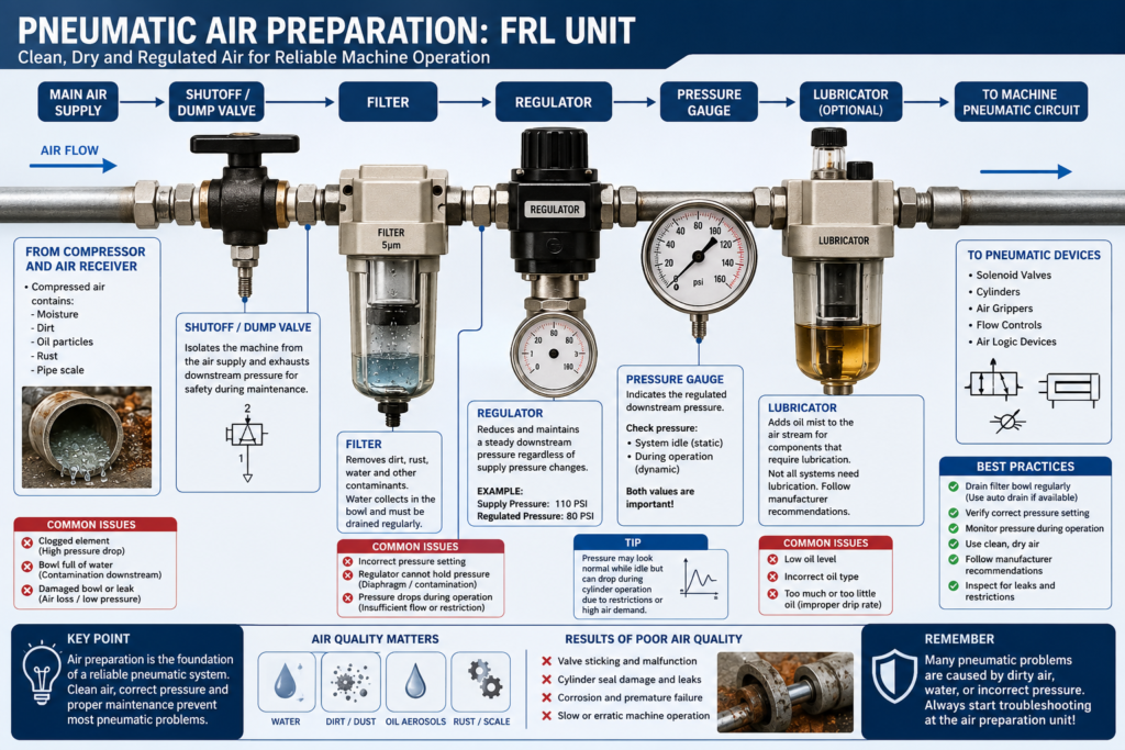
The typical air preparation path is:
Main Air Supply → Isolation Valve → Filter → Regulator → Pressure Gauge → Lubricator → Pneumatic Valves and Actuators
These components are frequently grouped together in an assembly known as an FRL unit.
FRL stands for:
- Filter
- Regulator
- Lubricator
However, many modern pneumatic systems use only a filter and regulator because several modern valves and cylinders are designed to operate without additional lubrication.
Why Does Compressed Air Require Preparation?
Compressed air is not automatically clean or dry.
Air entering a compressor may contain:
- Water vapor
- Dust
- Oil particles
- Rust
- Pipe contamination
- Other airborne particles
Compression also increases the concentration of moisture and contaminants.
Without proper treatment, these contaminants can enter the machine and cause:
- Sticking pneumatic valves
- Damaged cylinder seals
- Corrosion
- Blocked flow controls
- Slow cylinder movement
- Inconsistent machine operation
- Premature component failure
Air preparation protects the pneumatic system and improves machine reliability.
The Compressed Air Path
A typical industrial pneumatic system may follow this sequence:
Air Compressor
      ↓
Air Receiver Tank
      ↓
Air Dryer
      ↓
Plant Distribution Piping
      ↓
Machine Isolation Valve
      ↓
Filter
      ↓
Regulator
      ↓
Lubricator, if required
      ↓
Solenoid Valve Manifold
      ↓
Pneumatic Cylinders and Actuators
Each stage performs a different function.
1. Air Compressor
The air compressor converts electrical or mechanical energy into compressed-air energy.
The compressor pulls atmospheric air into the system, compresses it, and sends it to a receiver tank or distribution system.
The compressor is normally part of the plant utility system rather than the individual machine.
Common compressor-related problems include:
- Low plant air pressure
- Excessive moisture
- Oil contamination
- Overheating
- Pressure fluctuations
- Insufficient compressor capacity
A machine may experience pneumatic problems even when none of its local components are defective if the plant air supply is unstable.
2. Air Receiver Tank
The air receiver stores compressed air and helps stabilize system pressure.
Its functions include:
- Providing temporary air capacity
- Reducing pressure fluctuations
- Allowing moisture to separate
- Reducing frequent compressor cycling
Water can collect inside the receiver tank and must be drained according to the plant maintenance procedure.
3. Air Dryer
Compressed air contains moisture.
When compressed air cools, water vapor can condense inside piping, filters, valves, and cylinders.
An air dryer removes moisture before the air enters the plant distribution system.
Common dryer types include:
- Refrigerated air dryers
- Desiccant air dryers
- Membrane air dryers
For many general industrial applications, refrigerated dryers are commonly used.
Applications requiring extremely dry air may use desiccant dryers.
Without proper drying, moisture may cause:
- Internal corrosion
- Valve spool sticking
- Frozen pneumatic lines
- Contaminated instruments
- Damaged seals
- Unstable process control
4. Machine Isolation and Dump Valve
Before air reaches the FRL unit, many machines include a manual isolation valve or safety exhaust valve.
This device allows the pneumatic supply to be disconnected from the machine.
When properly designed, a dump valve performs two actions:
- Blocks incoming compressed air
- Exhausts trapped downstream pressure
This is important because shutting off the air supply does not always remove stored pneumatic energy.
A cylinder, accumulator, hose, or valve manifold may remain pressurized after the supply valve is closed.
Never assume that a pneumatic system is safe only because the main air valve is closed. Follow the approved lockout/tagout and stored-energy procedures for the equipment.
5. Pneumatic Filter
The filter removes contamination from the compressed-air supply.
Depending on its design and rating, a filter may remove:
- Dirt
- Rust
- Pipe scale
- Water droplets
- Oil aerosols
- Other solid particles
The filter normally contains:
- Filter element
- Bowl
- Water separator
- Manual or automatic drain
How the Filter Works
Compressed air enters the filter and is directed into a swirling motion.
This motion helps separate heavier water droplets and particles from the air.
The contaminants fall into the filter bowl.
The remaining air passes through the filter element before continuing downstream.
Filter Bowl Inspection
The filter bowl should be inspected for:
- Water accumulation
- Dirt
- Oil
- Cracks
- Damage
- Drain operation
A bowl filled with water or contamination can reduce airflow and allow contaminants to pass downstream.
Some bowls use a manual drain.
Others use an automatic drain that releases accumulated water without technician intervention.
Common Filter Problems
Clogged Filter Element
Symptoms:
- Low downstream pressure
- Slow cylinder movement
- Pressure drops during machine operation
- Multiple pneumatic devices operating poorly
Full Filter Bowl
Symptoms:
- Water entering downstream components
- Valve contamination
- Corrosion
- Irregular operation
Leaking Bowl or Seal
Symptoms:
- Audible air leak
- Constant pressure loss
- Compressor cycling
- Reduced machine pressure
6. Pressure Regulator
The pressure regulator reduces incoming air pressure to a controlled downstream value.
For example:
Plant Air Supply: 110 PSI

Machine Regulator Setting: 80 PSI
The regulator helps maintain stable machine pressure even when the upstream supply changes within its operating range.
The regulator normally includes:
- Adjustment knob
- Internal spring
- Diaphragm
- Valve mechanism
- Pressure gauge connection
Why Pressure Regulation Is Important
Not every pneumatic device should operate at full plant pressure.
Too much pressure may cause:
- Excessive cylinder force
- Hard mechanical impacts
- Premature seal wear
- Damaged machine components
- Unsafe movement
- Excessive air consumption
Too little pressure may cause:
- Cylinder failure to complete its stroke
- Weak clamping force
- Slow movement
- Failed sequence transitions
- Intermittent sensor feedback
- Machine timeout faults
The correct pressure should be based on the machine design and manufacturer specifications.
Adjusting a Pneumatic Regulator
Many regulators use a push-to-lock or pull-to-adjust knob.
A typical adjustment procedure is:
- Unlock or pull the adjustment knob.
- Turn clockwise to increase pressure.
- Turn counterclockwise to decrease pressure.
- Cycle or vent the downstream system when reducing pressure.
- Confirm the final pressure on the gauge.
- Lock the adjustment knob.
When reducing pressure, the gauge may not immediately decrease if pressure remains trapped downstream.
The system may need to consume or exhaust air before the lower setting appears.
Never increase pressure simply to compensate for a mechanical problem without confirming the approved pressure setting.
7. Pressure Gauge
The pressure gauge displays the regulated downstream pressure.
Common units include:
- PSI
- bar
- kPa
- MPa
For example:
80 PSI ≈ 5.5 bar
The gauge is an important troubleshooting tool, but it must be interpreted correctly.
A normal static pressure reading does not always mean that sufficient airflow is available during machine operation.
The system may show 80 PSI while idle but drop significantly when several cylinders operate.
This is known as pressure drop under demand.
Static Pressure vs Dynamic Pressure
Static Pressure
Pressure measured when the pneumatic system is not consuming significant airflow.
Dynamic Pressure
Pressure measured while cylinders, valves, or air devices are operating.
A machine may have acceptable static pressure but poor dynamic pressure because of:
- Restricted tubing
- Undersized fittings
- Clogged filter
- Partially closed isolation valve
- Damaged hose
- High air demand
- Insufficient plant supply
Dynamic pressure is often more useful than static pressure when troubleshooting slow or weak pneumatic motion.
8. Lubricator
A lubricator adds a controlled oil mist into the compressed-air stream.
The oil is carried downstream to components that require continuous lubrication.
Not every pneumatic system requires a lubricator.
Many modern pneumatic components are pre-lubricated and designed for non-lubricated operation.
Adding oil to a system that was designed to operate without it may:
- Contaminate products
- Affect instruments
- Damage certain components
- Create maintenance dependency
- Wash away original factory grease
Once some pneumatic systems are operated with added lubrication, they may need continuous lubrication afterward.
Always follow the equipment and component manufacturer requirements.
Lubricator Inspection
Check:
- Correct oil type
- Oil level
- Drip rate
- Bowl condition
- Airflow direction
- Leaks
Do not use random machine oil or hydraulic oil unless it is specifically approved for the lubricator.
Filter-Regulator vs Full FRL Assembly
Many machines use a combination assembly containing only:
- Filter
- Regulator
- Pressure gauge
This may be called:
- Filter-regulator
- Air preparation unit
- Service unit
- Pneumatic preparation assembly
A full FRL includes:
- Filter
- Regulator
- Lubricator
The correct configuration depends on the machine and the pneumatic components being used.
Airflow Direction Matters
Air preparation components are designed for a specific airflow direction.
Most components include an arrow molded or printed on the body.
Example:
INLET → FILTER → REGULATOR → OUTLET
Installing a regulator, filter, or lubricator backward may cause:
- Incorrect regulation
- Restricted flow
- Internal damage
- Improper draining
- Component malfunction
Always verify the airflow arrow during installation or replacement.
Pneumatic Tubing and Fittings
Air preparation is only effective if the downstream tubing and fittings are correctly sized and installed.
Common tubing problems include:
- Kinked tubing
- Crushed tubing
- Incorrect tube diameter
- Loose push-to-connect fittings
- Damaged O-rings
- Excessively long tubing runs
- Contamination inside the tubing
A small restriction can reduce airflow even when the pressure gauge appears normal.
Pressure and flow are related, but they are not the same.
Pressure represents pneumatic force potential.
Flow determines how quickly the air can fill or exhaust a cylinder.
A system may have sufficient pressure but insufficient flow.
Real Industrial Example
Consider a machine with three pneumatic cylinders.
The operator reports:
“All three cylinders are moving slowly.”
Because several cylinders are affected at the same time, the technician should first inspect components shared by all three devices.
Possible shared causes include:
- Low plant air pressure
- Partially closed isolation valve
- Clogged main filter
- Incorrect regulator setting
- Water-filled filter bowl
- Restricted main supply tubing
Replacing individual solenoid valves or cylinders would not be the best first step because the problem affects the entire pneumatic circuit.
Troubleshooting Example: Cylinder Moves Slowly
Step 1 — Check the Regulator Gauge
Is the machine pressure at the approved setting?
- If no, verify the regulator and plant supply.
- If yes, continue troubleshooting.
Step 2 — Observe Pressure During Motion
Does the pressure drop significantly when the cylinder operates?
- If yes, suspect an airflow restriction or insufficient supply.
- If no, continue troubleshooting.
Step 3 — Inspect the Filter
Check for:
- Water
- Contamination
- Clogged element
- Damaged bowl
- Drain problems
Step 4 — Verify the Isolation Valve
Confirm the machine air valve is completely open.
A partially open valve can restrict airflow.
Step 5 — Check Tubing and Fittings
Look for:
- Kinks
- Crushed tubing
- Leaks
- Incorrect tubing size
- Blocked fittings
Step 6 — Inspect Local Flow Controls
If only one cylinder is slow, the problem may be in its individual flow-control valve rather than the main air preparation unit.
Common Symptoms and Possible Causes
| Symptom | Possible Cause |
|---|---|
| All cylinders move slowly | Low supply pressure, clogged main filter, restricted supply |
| One cylinder moves slowly | Local flow control, tubing restriction, cylinder problem |
| Pressure gauge reads low | Regulator setting, supply problem, major leak |
| Pressure is normal while idle but drops during movement | Insufficient airflow or excessive demand |
| Water appears in valves or tubing | Dryer problem, full filter bowl, drain failure |
| Regulator cannot maintain pressure | Damaged diaphragm, contamination, undersized regulator |
| Constant air leak near FRL | Bowl seal, fitting, regulator relief, damaged component |
| Cylinder lacks force | Low regulated pressure, excessive load, worn cylinder seal |
| Valves stick intermittently | Moisture, contamination, incorrect lubrication |
Recommended Technician Inspection Checklist
Before troubleshooting individual pneumatic valves or cylinders, verify:
- Main air supply is available
- Isolation valve is fully open
- Safety dump valve is reset
- Regulator pressure is correct
- Pressure remains stable during operation
- Filter bowl is not full
- Filter element is not clogged
- Dryer is operating correctly
- Tubing is not kinked or damaged
- No major leaks are present
- Lubricator condition is correct, if used
- Airflow direction is correct
This inspection can prevent unnecessary replacement of PLC modules, solenoid coils, valves, or cylinders.
Key Troubleshooting Principle
When multiple pneumatic devices fail at the same time, inspect the shared air supply first.
When only one device fails, inspect its local circuit.
This principle helps separate system-level faults from component-level faults.
Example:
Multiple Cylinders Affected
        ↓
Check Main Air Supply, FRL, and Distribution

Only One Cylinder Affected
        ↓
Check Local Valve, Tubing, Flow Control, Sensor, and Cylinder
Conclusion
Proper air preparation is the foundation of a reliable pneumatic system.
The compressor provides the energy, but the air dryer, filter, regulator, pressure gauge, and lubricator determine whether that energy reaches the machine in a usable condition.
For an Automation Technician, the FRL assembly is not just a group of air components. It is a critical troubleshooting point that can affect every pneumatic valve, actuator, and cylinder connected downstream.
Before changing a solenoid valve or modifying PLC logic, always confirm:
- Is the air clean?
- Is the air dry?
- Is the pressure correct?
- Does the pressure remain stable during machine operation?
- Is enough airflow reaching the pneumatic circuit?
A correct diagnosis begins with understanding the complete energy path from the plant air supply to the final mechanical movement.
In the next post, we will study pneumatic directional control valves, including 3/2, 5/2, and 5/3 valve configurations, port identification, operating positions, and their industrial applications.