1. Industrial Pneumatics Fundamentals: From Compressed Air to Machine Motion
Introduction
In industrial automation, pneumatic systems are one of the most commonly used technologies for creating fast, reliable, and repetitive mechanical movement.
From simple box pushers on conveyors to complex filling, packaging, and assembly machines, pneumatics plays a critical role in modern manufacturing.
Many technicians see only the final action: a cylinder extending or retracting. However, behind that movement there is a complete system working together:
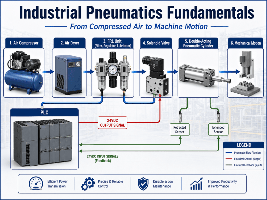
Compressed Air → Air Preparation → Control Valve → Solenoid → Pneumatic Cylinder → Sensor Feedback → PLC Control
Understanding this relationship is essential for any Automation Technician because it allows faster troubleshooting and better understanding of machine operation.
What Is a Pneumatic System?
A pneumatic system uses compressed air as an energy source to create mechanical movement.
Unlike an electric motor, where electrical energy is converted directly into rotary motion, pneumatic systems use air pressure to create linear motion through actuators such as cylinders.
Example:
A PLC receives a signal from a sensor indicating that a product has reached the correct position.
The PLC activates an output:
PLC Output ON

      |

Solenoid Valve Energized

      |

Air Flow Direction Changes

      |

Pneumatic Cylinder Extends

      |

Mechanical Movement Occurs
The final action could be:
- Stopping a product
- Pushing a box
- Clamping a part
- Opening a door
- Positioning a machine component
Why Are Pneumatic Systems Used in Automation?
1. High-Speed Operation
Pneumatic cylinders can perform fast repetitive movements, making them ideal for production equipment.
Common applications:
- Pick and place systems
- Packaging machines
- Bottle fillers
- Wrapping machines
- Conveyor systems
2. Simple Design
A basic pneumatic system consists of a few main components:
- Air supply
- Valve
- Cylinder
- Sensors
- PLC control
This simplicity makes maintenance and troubleshooting easier.
3. Safety Advantages
Depending on the design, pneumatic systems can move to a safe condition when electrical power is removed.
For example:
A valve configuration can allow a cylinder to return to a safe position when the control signal is lost.
4. Cost Effective Solution
Compared with servo systems or hydraulic systems, pneumatics is often a lower-cost solution for simple motion applications.
Basic Architecture of an Industrial Pneumatic System
Let’s follow the complete air path.
1. Air Compressor
The compressor generates compressed air by converting electrical energy into stored pneumatic energy.
Electrical Energy

        |

Air Compressor

        |

Compressed Air
2. Air Dryer
Compressed air contains moisture that can damage pneumatic components.
The air dryer removes water to prevent:
- Corrosion
- Valve failures
- Sensor problems
- Contamination
3. FRL Unit
FRL stands for:
Filter – Regulator – Lubricator
Many modern systems use only Filter and Regulator.
Filter
Removes contaminants from the air:
- Dust
- Particles
- Water
Regulator
Controls the operating pressure of the pneumatic system.
Example:
Input pressure:
120 PSI
Regulated pressure:
80 PSI
The regulator ensures the machine receives stable pressure.
Lubricator
Adds oil mist to the air stream for components that require lubrication.
(Some modern pneumatic systems are designed to operate without lubrication.)
4. Solenoid Valve
The solenoid valve is the point where electrical control becomes pneumatic action.
The PLC does not directly move the cylinder.
The PLC only controls the electrical coil that changes the valve position.
Example:
PLC 24VDC Output

        |

Solenoid Coil

        |

Valve Spool Movement

        |

Air Direction Changes

        |

Cylinder Movement
5. Pneumatic Cylinder
The cylinder converts air pressure into mechanical movement.
Common cylinder types:
Single Acting Cylinder
Uses compressed air in one direction and a spring for return movement.
Applications:
- Small pushers
- Simple mechanisms
Double Acting Cylinder
Uses compressed air for both extension and retraction.
Applications:
- Clamps
- Stops
- Pushers
- Industrial doors
Real Industrial Automation Example
Imagine a conveyor transporting boxes.
The goal:
Stop a box in a precise position for an operation.
Step 1 — Product Detection
A photoeye detects the box.
Photoeye ON

PLC Input = TRUE
Step 2 — PLC Logic Decision
The PLC evaluates the conditions.
Example:
Box Present

AND

System Ready

=

Extend Command
Step 3 — PLC Activates Output
The PLC turns ON the output:
DO_Stopper_Extend = ON
Step 4 — Solenoid Valve Activates
The solenoid coil energizes.
The valve changes position and redirects compressed air.
Step 5 — Cylinder Extends
The pneumatic cylinder moves and stops the box.
Step 6 — Position Feedback
A sensor confirms the cylinder position.
Cylinder Extended Sensor

PLC Input = TRUE
The PLC now knows the movement was completed successfully.
The Connection Between Pneumatics and PLC Control
As Automation Technicians, we must understand three different levels.
Level 1 — Electrical Control
PLC components:
- Inputs
- Program Logic
- Outputs
Level 2 — Pneumatic Control
Components:
- Solenoid valves
- Regulators
- Flow controls
- Pneumatic circuits
Level 3 — Mechanical Motion
Components:
- Cylinders
- Clamps
- Pushers
- Mechanical assemblies
A machine problem can exist at any of these levels.
Pneumatic Troubleshooting Example
Problem:
“The cylinder does not extend.”
Do not immediately assume the PLC is the problem.
Follow a structured troubleshooting process.
Step 1
Is the PLC activating the output?
YES → Continue troubleshooting
NO → Check PLC logic
Step 2
Does the solenoid valve receive voltage?
YES → Check valve operation
NO → Check wiring or PLC output
Step 3
Does the valve shift?
YES → Check air supply and cylinder
NO → Possible solenoid or valve failure
Step 4
Is the air pressure correct?
YES → Check mechanical issues
NO → Check pneumatic supply
Conclusion
Industrial pneumatics is not simply a cylinder moving back and forth.
It is a complete system where multiple technologies work together:
- Pneumatic energy
- Mechanical components
- Electrical control
- PLC programming
- Sensors
- Machine logic
For an Automation Technician, understanding this complete chain allows faster troubleshooting, better machine understanding, and more effective maintenance.
In the next articles, we will explore:
- Pneumatic valves
- Solenoid operation
- Cylinder fundamentals
- Sensors and feedback
- PLC Extend/Retract logic
- Pneumatic sequence control
- Real-world troubleshooting methods
The goal is not only to understand what the machine does, but also why it does it and how to diagnose it when something fails.