2. Main Parts of a PLC System
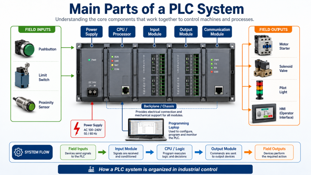
A PLC system is made of several hardware and software components that work together to control an industrial machine or process.
At a basic level, a PLC system receives information from field devices, processes that information through the control program, and then commands output devices.
Input Devices → Input Module → CPU / Logic Program → Output Module → Output DevicesA PLC is not just one box inside the control panel. It is a complete control system that includes the processor, input/output modules, power supply, memory, communication ports, programming software, and field wiring.
According to Programmable Logic Controllers, 6th Edition, a typical PLC can be divided into major parts such as the CPU, I/O section, power supply, and programming device. The I/O system is the interface between field devices and the controller.
1. CPU / Processor
The CPU, also called the processor, is the brain of the PLC.
It is responsible for:
Reading input status
Executing the user program
Making logic decisions
Updating outputs
Managing memory
Handling communication
Performing diagnostics
The CPU runs the PLC program continuously while the controller is in Run Mode.
For example, if a Start pushbutton is pressed, the CPU reads that input, solves the ladder logic, and decides whether the motor output should turn ON.
Simple example:
IF Start_PB is ON
AND Stop_PB is OK
THEN Motor_Command = ON
The CPU does not directly “think” like a human. It follows the programmed instructions exactly as written.
2. Power Supply
The PLC power supply provides the internal power required by the PLC processor and modules.
In many PLC systems, the power supply converts incoming power such as:
120 VAC
230 VAC
24 VDC
into the lower DC voltage needed by the internal PLC electronics.
Important note:
The PLC power supply usually powers the PLC electronics, but it does not always power the field devices.
In many industrial panels, field devices such as sensors, solenoids, relays, and pilot lights are powered by a separate 24 VDC or AC control power supply.
That means a technician should understand the difference between:
PLC internal power
Field device power
Control circuit power
This is very important during troubleshooting.
3. Input Modules
Input modules allow the PLC to receive signals from field devices.
Input devices tell the PLC what is happening in the machine.
Common PLC input devices include:
Start pushbuttons
Stop pushbuttons
Selector switches
Limit switches
Proximity sensors
Photoelectric sensors
Pressure switches
Level switches
Temperature switches
Motor overload auxiliary contacts
VFD running or fault contacts
The input module converts the field signal into a signal the PLC processor can understand.
For example:
24 VDC sensor signal → Input module → PLC memory bitIf a proximity sensor turns ON, the input module detects that voltage and the PLC stores that input as a logic 1.
If the sensor is OFF, the PLC stores it as a logic 0.
4. Output Modules
Output modules allow the PLC to control real-world devices.
Common PLC output devices include:
Pilot lights
Relays
Solenoids
Motor starters
Contactors
Horns
Stack lights
VFD start commands
Valve actuators
The PLC program decides when an output should turn ON or OFF. The output module then switches power to the field device or sends a control signal.
Example:
PLC logic true → Output module turns ON → Motor starter coil energizesIn many cases, a PLC output does not directly power a large device. Instead, it controls an interposing relay, contactor, or starter.
This protects the PLC output module and allows the system to control higher-current loads safely.
5. I/O Section
The I/O section is the part of the PLC system where field devices connect to the controller.
I/O means:
I = Inputs
O = Outputs
The I/O section can be:
Fixed I/O
Modular I/O
Remote / Distributed I/O
6. Fixed I/O
A fixed I/O PLC has the processor, power supply, inputs, and outputs built into one unit.
This type is common in smaller machines or simple control systems.
Advantages:
Lower cost
Compact size
Simple installation
Good for small applications
Limitations:
Less flexible
Limited number of I/O points
Harder to expand
If one section fails, the whole unit may need replacement
A small compact PLC or micro PLC is a common example of fixed I/O.
7. Modular I/O
A modular PLC uses separate modules that plug into a rack or chassis.
A typical modular PLC may include:
Power supply module
CPU module
Digital input module
Digital output module
Analog input module
Analog output module
Communication module
Specialty module
The modules connect through the backplane of the rack.
The backplane allows:
Power distribution to modules
Communication between modules
Data exchange with the CPU
Modular PLCs are more flexible because you can select the exact type and number of modules needed for the application.
For example:
Slot 0: CPU
Slot 1: 16-point digital input module
Slot 2: 16-point digital output module
Slot 3: Analog input module
Slot 4: Ethernet communication module
This type of system is common in larger industrial machines and production lines.
8. Remote or Distributed I/O
Remote I/O or distributed I/O means the input and output modules are located away from the main PLC processor.
Instead of running every field wire back to the main control panel, remote I/O can be installed closer to the machine.
Example:
Main PLC Panel → Ethernet/IP Network → Remote I/O Block Near ConveyorThis helps reduce:
Long cable runs
Panel wiring complexity
Installation time
Troubleshooting distance
Field wiring cost
Remote I/O is very common in modern industrial systems.
Examples include:
ArmorBlock I/O
POINT I/O
FLEX I/O
Remote racks
Distributed machine-mounted I/O
For an Automation Technician, remote I/O is important because a missing input or output may not be located in the main PLC panel. It may be on a remote module near the machine.
9. Backplane / Chassis
In a modular PLC, the backplane is the internal connection path inside the rack or chassis.
The backplane allows the CPU to communicate with the modules installed in the rack.
It also distributes internal power from the PLC power supply to the modules.
Think of the backplane like the PLC’s internal highway.
CPU ↔ Backplane ↔ Input Module
CPU ↔ Backplane ↔ Output Module
CPU ↔ Backplane ↔ Communication Module
If the backplane, chassis, or module connection has a problem, the CPU may not be able to communicate with one or more modules.
10. Memory
PLC memory stores the information needed for the controller to operate.
This includes:
User program
Input status
Output status
Timer values
Counter values
Data tags
Fault information
Configuration data
The PLC program is stored in memory and executed by the CPU.
In modern PLCs, memory may include different data types such as:
BOOL
SINT
INT
DINT
REAL
Timer structures
Counter structures
Arrays
User-defined tags
In simple terms:
BOOL = ON/OFF bit
DINT = whole number
REAL = decimal number
TIMER = timer data structure
COUNTER = counter data structure
11. Programming Device
A programming device is used to create, edit, download, upload, monitor, and troubleshoot the PLC program.
Today, this is usually a laptop with PLC programming software.
Examples:
Studio 5000 Logix Designer
RSLogix 500
Connected Components Workbench
TIA Portal
CODESYS
AutomationDirect software
With the programming device, a technician or engineer can:
Go online with the PLC
Monitor live ladder logic
Check input and output status
Upload the program from the PLC
Download a program to the PLC
Edit logic
Document tags and rung comments
Troubleshoot faults
Check communication status
For troubleshooting, the programming laptop is one of the most valuable tools a technician can have.
12. Communication Ports and Network Modules
Modern PLCs communicate with many industrial devices.
Common communication methods include:
Ethernet/IP
Modbus TCP
Serial communication
DeviceNet
ControlNet
PROFINET
Remote I/O networks
PLC communication may be used for:
HMI connection
SCADA connection
VFD control
Remote I/O
PLC-to-PLC messaging
Data collection
Barcode readers
Vision systems
Industrial switches
Example:
PLC ↔ Ethernet Switch ↔ HMI
PLC ↔ Ethernet Switch ↔ VFD
PLC ↔ Ethernet Switch ↔ Remote I/O
PLC ↔ SCADA / Ignition
Communication is one of the reasons PLCs are so powerful in modern industrial automation.
13. HMI — Human Machine Interface
An HMI is not the PLC itself, but it is commonly part of the PLC control system.
The HMI allows the operator to interact with the machine.
An HMI can display:
Start / Stop buttons
Machine status
Alarms
Fault messages
Process values
Trends
Setpoints
Manual controls
Production counts
The HMI communicates with the PLC by reading and writing PLC tags.
Example:
Operator presses Start on HMI
HMI writes Start_Command tag
PLC reads Start_Command
PLC turns on motor logic if permissives are OK
The HMI is the operator’s window into the PLC system.
14. Field Devices
Field devices are the real-world devices connected to the PLC system.
They are usually mounted on the machine, conveyor, tank, motor, valve, or process equipment.
Field devices include both inputs and outputs.
Input Field Devices
Pushbuttons
Sensors
Switches
Transmitters
Overload contacts
Feedback contacts
Output Field Devices
Relays
Solenoids
Contactors
Pilot lights
Stack lights
VFD commands
Actuators
A PLC cannot control the process without field devices. The PLC program depends on real-world feedback.
15. Terminal Blocks and Field Wiring
Field wiring connects sensors and output devices to the PLC system.
Terminal blocks are used to organize and land wires inside the control panel.
Good wiring practices make troubleshooting easier.
A clean PLC panel should have:
Labeled wires
Organized terminal blocks
Separated AC and DC wiring
Proper grounding
Correct fusing
Correct wire colors
Updated electrical drawings
Clear I/O labeling
A good PLC program is important, but a messy panel can still create major troubleshooting problems.
Simple PLC System Example
Imagine a small motor control system.
Inputs
Start Pushbutton
Stop Pushbutton
Motor Overload Contact
Motor Running Feedback
PLC Logic
If Start is pressed
AND Stop is OK
AND Overload is healthy
THEN command the motor starter
Outputs
Motor Starter Coil
Run Pilot Light
Fault Pilot Light
HMI Display
Motor Status: Running / Stopped
Fault Status: Overload Fault
Start / Stop Buttons
Runtime Counter
This is a simple example, but the structure is similar in many real industrial machines.
PLC System Flow
Field Input Device
        ↓
Input Module
        ↓
Input Memory / Tag
        ↓
CPU Executes Program
        ↓
Output Memory / Tag
        ↓
Output Module
        ↓
Field Output Device
This flow is the foundation of PLC control.
Automation Technician Notes
When troubleshooting a PLC system, do not only look at the ladder logic.
A real technician checks the complete path:
1. Is the field device working?
2. Is the correct voltage present?
3. Is the input module seeing the signal?
4. Is the PLC logic using the correct tag?
5. Is the output being commanded?
6. Is the output module turning ON?
7. Is field power available to the load?
8. Is the relay, solenoid, contactor, or VFD working?
9. Is there a fault, interlock, or permissive blocking the output?
A PLC problem is not always a programming problem.
Many PLC issues are caused by:
Loose wire
Bad sensor
Blown fuse
Missing common
Wrong voltage
Failed relay
Bad output point
Network fault
Incorrect field feedback
The best troubleshooting approach is to follow the signal from the field device to the PLC and back to the output device.
Main PLC Parts Summary
| PLC Part | Main Function |
|---|---|
| CPU / Processor | Executes the PLC program and makes logic decisions |
| Power Supply | Provides internal power to the PLC system |
| Input Module | Receives signals from field devices |
| Output Module | Sends commands to output devices |
| Backplane / Chassis | Connects modules and allows communication |
| Memory | Stores program, data, tags, and status |
| Programming Device | Used to program, monitor, and troubleshoot the PLC |
| Communication Module | Connects PLC to networks and external devices |
| HMI | Allows operator interaction with the machine |
| Field Devices | Real-world sensors, switches, actuators, and loads |
| Terminal Blocks | Organize field wiring inside the panel |
Key Terms
| Term | Meaning |
|---|---|
| CPU | The processor or brain of the PLC |
| I/O | Inputs and outputs |
| Input Module | Module that receives field signals |
| Output Module | Module that controls field devices |
| Backplane | Internal rack connection path |
| Fixed I/O | PLC with built-in inputs and outputs |
| Modular I/O | PLC with removable modules |
| Remote I/O | I/O located away from the main PLC |
| Field Device | Real-world device connected to the PLC |
| HMI | Operator interface screen |
| Tag | Named memory location in the PLC |
| Programming Device | Laptop or terminal used to program the PLC |
Final Thoughts
Understanding the main parts of a PLC system is one of the first steps in becoming confident with industrial automation.
A PLC system is more than just a processor. It includes input modules, output modules, power supplies, communication networks, field devices, wiring, programming software, and often an HMI.
For an Automation Technician, the most important idea is this:
The PLC is only one part of the control system. Real troubleshooting means understanding the full path from the field device, through the PLC logic, and back to the output device.
Once you understand how each part works together, PLC troubleshooting becomes much easier and more logical.