13. Timers in Studio 5000: TON Explained for Technicians
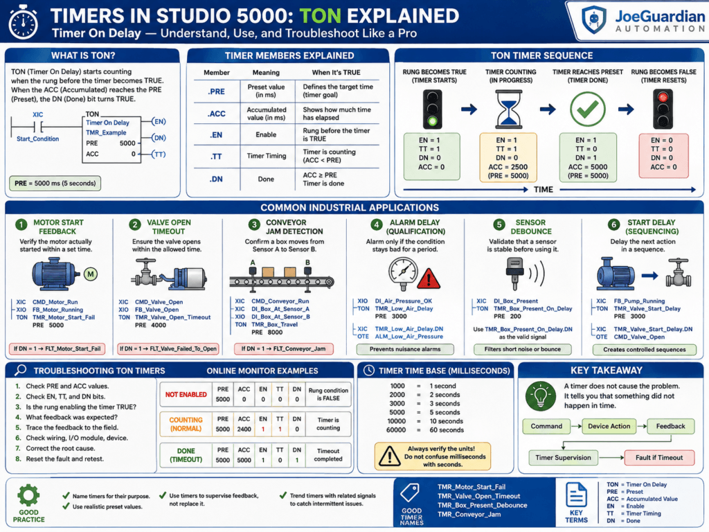
Timers are everywhere in industrial automation.
A motor may need a few seconds to prove that it started. A valve may need time to reach its open position. A photoeye signal may need a short debounce delay. A conveyor may need a timeout before declaring a jam.
In Studio 5000, one of the most common instructions used for this purpose is the TON — Timer On Delay.
For an automation technician, understanding the TON instruction is critical because many machine faults are not caused by a bad timer. The timer is often only telling you that something else did not happen within the expected amount of time.
A good technician learns to read the timer as part of the complete signal path:
Command → Device Action → Feedback → Timer → Fault DecisionWhat Is a TON Timer?
TON stands for:
Timer On DelayThe timer begins counting when the logic before the TON instruction becomes true.
Example:
XIC    CMD_Motor_Start
TON    TMR_Motor_Start_Delay
       PRE 5000
       ACC 0
If CMD_Motor_Start becomes true, the timer begins accumulating time.
If the preset is:
5000 msthe timer will reach its preset after:
5 secondsWhen the accumulated value reaches the preset, the timer’s .DN bit becomes true.
Understanding the Main Timer Members
A Studio 5000 timer is more than just a single value.
A timer tag contains several members.
For example:
TMR_Motor_Startmay contain:
TMR_Motor_Start.PRE
TMR_Motor_Start.ACC
TMR_Motor_Start.EN
TMR_Motor_Start.TT
TMR_Motor_Start.DN
These members are extremely important for troubleshooting.
.PRE — Preset
The preset defines how long the timer must count before it is done.
Example:
TMR_Motor_Start.PRE = 5000This means:
5000 ms = 5 secondsAnother example:
TMR_Valve_Timeout.PRE = 10000means:
10 seconds.ACC — Accumulated Value
The accumulated value shows how much time has already passed.
For example:
PRE = 5000
ACC = 3200
The timer has been active for:
3.2 secondsbut has not yet reached its preset.
When:
ACC = 5000the timer becomes done.
.EN — Enable Bit
The .EN bit becomes true when the rung controlling the timer is true.
Think of .EN as:
The timer instruction is currently enabled.Example:
TMR_Motor_Start.ENIf this bit is true, the timer rung is true.
.TT — Timer Timing Bit
The .TT bit means:
Timer TimingIt is true while the timer is actively counting.
Normally:
EN = 1
TT = 1
DN = 0
while the timer is counting.
Once the timer reaches its preset:
EN = 1
TT = 0
DN = 1
This is extremely useful when diagnosing timing behavior.
.DN — Done Bit
The .DN bit becomes true when:
ACC >= PREExample:
XIC    TMR_Motor_Start.DN
OTE    ALM_Motor_Start_Timeout
When the timer reaches its preset, the alarm becomes active.
TON Timer Sequence
Here is a simple way to visualize the timer.
Rung becomes true
EN = 1
TT = 1
DN = 0
The timer begins counting.
Timer is still counting
Example:
PRE = 5000
ACC = 2500
Status:
EN = 1
TT = 1
DN = 0
Timer reaches preset
PRE = 5000
ACC = 5000
Status:
EN = 1
TT = 0
DN = 1
Rung becomes false
For a TON timer, the timer resets.
Typically:
ACC = 0
EN = 0
TT = 0
DN = 0
Industrial Example 1 — Motor Start Feedback
This is one of the most important uses of a timer.
Suppose the PLC commands a motor to start.
CMD_Motor_RunThe motor starter or VFD should return feedback:
FB_Motor_RunningBut the motor may require a short amount of time to start.
We do not want to declare a fault immediately.
So we use a timer.
Example:
XIC    CMD_Motor_Run
XIO    FB_Motor_Running
TON    TMR_Motor_Start_Fail
       PRE 5000
Meaning:
Motor is commanded ON
AND
Motor running feedback is still OFF
Start the timer.
If the feedback appears before 5 seconds, the timer resets.
If the feedback does not appear:
TMR_Motor_Start_Fail.DN = 1Then we can generate:
FLT_Motor_Start_FailTechnician Troubleshooting Perspective
If you see:
FLT_Motor_Start_Faildo not immediately assume the timer is wrong.
Trace the complete signal path.
PLC Command
↓
Output Module
↓
Contactor / VFD
↓
Motor
↓
Auxiliary Contact / Drive Feedback
↓
PLC Input
↓
FB_Motor_Running
Possible causes include:
- VFD fault
- overload trip
- contactor did not energize
- motor disconnect open
- wiring issue
- auxiliary contact failure
- PLC input problem
- network communication loss
- motor actually failed to start
The timer may simply be doing exactly what it was designed to do.
Industrial Example 2 — Valve Open Timeout
Imagine a pneumatic valve.
The PLC sends:
CMD_Valve_OpenThe valve should eventually return:
FB_Valve_OpenExample logic:
XIC    CMD_Valve_Open
XIO    FB_Valve_Open
TON    TMR_Valve_Open_Timeout
       PRE 4000
If the valve does not reach the open limit switch within 4 seconds:
TMR_Valve_Open_Timeout.DNcan trigger:
FLT_Valve_Failed_To_OpenWhat Should a Technician Check?
If this timer reaches .DN, check:
Air pressure
Solenoid output
Solenoid coil
Valve actuator
Mechanical binding
Open limit switch
Limit switch wiring
PLC input
Again, the timer is not necessarily the problem.
The timer tells you:
The expected feedback did not arrive in time.Industrial Example 3 — Conveyor Jam Detection
Suppose a conveyor moves a box from Sensor A to Sensor B.
When the conveyor starts, Sensor B should become active within 8 seconds.
Logic might look like:
XIC    CMD_Conveyor_Run
XIC    DI_Box_At_Sensor_A
XIO    DI_Box_At_Sensor_B
TON    TMR_Box_Travel
       PRE 8000
If the box does not reach Sensor B:
TMR_Box_Travel.DN = 1then:
FLT_Conveyor_Jamcan become active.
Industrial Example 4 — Alarm Delay
Not every abnormal signal should create an immediate alarm.
Suppose low air pressure occasionally drops for a fraction of a second.
Without a delay:
Low Air Pressure
↓
Alarm immediately
This may create nuisance alarms.
Instead:
XIO    DI_Air_Pressure_OK
TON    TMR_Low_Air_Delay
       PRE 3000
Then:
XIC    TMR_Low_Air_Delay.DN
OTE    ALM_Low_Air_Pressure
The pressure must remain bad for 3 seconds before generating the alarm.
This is called alarm qualification.
Industrial Example 5 — Sensor Debounce
Sensors can occasionally flicker because of:
- vibration
- product movement
- electrical noise
- mechanical bouncing
- marginal alignment
A timer can confirm that the signal remains stable.
Example:
XIC    DI_Box_Present
TON    TMR_Box_Present_On_Delay
       PRE 200
Then use:
TMR_Box_Present_On_Delay.DNas the validated signal.
For example:
DI_Box_Present_ValidA 200 ms delay can eliminate very short signal changes.
Important Note About Debounce
A complete debounce strategy may require both:
ON delayand:
OFF delaybecause a sensor can flicker in both directions.
A single TON only validates one side of the transition.
That becomes more important in higher-quality industrial logic.
Industrial Example 6 — Start Delay
Sometimes a machine must wait before starting another device.
Example:
Pump starts
↓
Wait 3 seconds
↓
Open valve
Logic:
XIC    FB_Pump_Running
TON    TMR_Valve_Start_Delay
       PRE 3000
Then:
XIC    TMR_Valve_Start_Delay.DN
OTE    CMD_Valve_Open
This creates a controlled sequence.
Timer Presets from the HMI
The preset does not always need to be a fixed number.
You may have:
HMI_Start_Delay_msand move it into:
TMR_Start_Delay.PREExample:
MOV    HMI_Start_Delay_ms
       TMR_Start_Delay.PRE
This lets the operator or technician adjust the delay from the HMI.
Be Careful with Units
One of the most common timer mistakes is misunderstanding the time base.
In Logix 5000 timer values are normally expressed in milliseconds.
So:
1000 = 1 second
5000 = 5 seconds
10000 = 10 seconds
60000 = 60 seconds
A programmer intending to create a 10-second timer but entering:
10would create a very short delay.
Always verify the units.
Troubleshooting a Timer Online
When you go online with Studio 5000, watch these values:
PRE
ACC
EN
TT
DN
Suppose you have:
PRE = 5000
ACC = 0
EN = 0
TT = 0
DN = 0
The timer is not being enabled.
Look to the left side of the rung.
Something before the timer is false.
If you see:
PRE = 5000
ACC = 2400
EN = 1
TT = 1
DN = 0
the timer is working normally and currently counting.
If you see:
PRE = 5000
ACC = 5000
EN = 1
TT = 0
DN = 1
the timeout has completed.
Now determine why the condition controlling the timer is still true.
The Timer Is Often a Symptom, Not the Cause
This is one of the most important troubleshooting lessons.
Suppose you see:
TMR_Valve_Open_Timeout.DN = 1Do not think:
The timer failed.
Instead think:
Why did the valve fail to produce its feedback before the timer expired?
That mindset changes troubleshooting completely.
Using Trends to Troubleshoot Timers
Studio 5000 Trends can be extremely helpful when investigating intermittent timer faults.
You might trend:
CMD_Motor_Run
FB_Motor_Running
TMR_Motor_Start_Fail.ACC
TMR_Motor_Start_Fail.DN
FLT_Motor_Start_Fail
Then you can see:
Command starts
↓
Timer begins
↓
Feedback arrives
or:
Command starts
↓
Timer reaches preset
↓
Feedback never arrives
↓
Fault activates
This is especially valuable for intermittent problems that disappear before a technician reaches the machine.
We will cover Trending in much more detail later in this series.
Good Timer Naming
Avoid names like:
Timer1
Timer2
T4
Delay1
Use names that explain the timer’s function.
Good examples:
TMR_Motor_Start_Fail
TMR_Valve_Open_Timeout
TMR_Low_Air_Delay
TMR_Box_Present_Debounce
TMR_Conveyor_Jam
TMR_Auto_Close_Delay
A technician should be able to understand the purpose before opening the rung.
Good Timer Logic Structure
A good timer should normally answer a clear question.
For example:
Motor commanded to run
AND
Motor feedback missing
FOR
5 seconds
Then:
Motor Start FailureThat logic reads almost like English.
Common Timer Mistakes
1. Timer Starts Under the Wrong Conditions
If the timer starts when it should not, inspect the logic before it.
2. Preset Is Too Short
Real devices need time to respond.
A valve that normally takes 3 seconds should probably not have a 1-second timeout.
3. Preset Is Too Long
A 60-second timeout for a motor start failure may delay fault detection unnecessarily.
The timing should match the real machine.
4. Using the Timer Instead of Feedback
Do not assume:
5 seconds passed = motor is runningwhen real feedback is available.
Better:
Command
↓
Motor feedback
Use timers to supervise feedback, not replace it.
5. Using Only .DN Without Understanding Why It Became True
Always inspect:
EN
TT
ACC
PRE
and the logic controlling the timer.
6. Confusing Milliseconds and Seconds
Always verify the preset units.
Programmer Perspective
Timers become much more powerful when used as part of a structured machine design.
Good industrial logic often follows this pattern:
Command
↓
Permissives
↓
Output
↓
Feedback
↓
Prove Timer
↓
Fault
For example:
CMD_Conveyor_Run
↓
DO_Conveyor_Run
↓
FB_Conveyor_Running
↓
TMR_Conveyor_Start_Fail
↓
FLT_Conveyor_Start_Fail
This creates logic that is easier to troubleshoot, document, and maintain.
Technician Mindset
When troubleshooting timers, ask:
What condition started this timer?Then:
What event was supposed to stop or reset it?Then:
Why did that event not happen?That approach is much more powerful than simply resetting the fault.
Practical Troubleshooting Flow
For a timer-related fault, follow this sequence:
1. Identify the active timer.

2. Check PRE and ACC.

3. Check EN, TT, and DN.

4. Inspect the rung conditions.

5. Determine what feedback was expected.

6. Trace the feedback to the field.

7. Check wiring, I/O, device, and communication.

8. Correct the root cause.

9. Reset the fault.

10. Verify the machine completes the sequence normally.
Example Complete Motor Start Fault
The logic concept may look like this:
CMD_Motor_Run
AND
NOT FB_Motor_Running
↓
TON TMR_Motor_Start_Fail
PRE = 5000
Then:
TMR_Motor_Start_Fail.DN
↓
FLT_Motor_Start_Fail
The complete industrial signal chain becomes:
PLC Command
↓
Output
↓
VFD / Contactor
↓
Motor
↓
Running Feedback
↓
PLC Input
↓
Timer Supervision
↓
Fault
That is much closer to how real industrial machines are designed.
Key Terms
TON = Timer On Delay

PRE = Preset

ACC = Accumulated Value

EN = Enable

TT = Timer Timing

DN = Done

Timeout = Maximum permitted response time

Feedback = Signal confirming that the commanded device actually responded
Final Thoughts
The TON instruction is simple to use, but understanding how it fits into a real machine is much more important than memorizing its parameters.
For a programmer, TON provides controlled delays and timeout supervision.
For an automation technician, TON provides valuable diagnostic information.
When you see a timer reach .DN, do not immediately blame the timer.
Ask:
What was the PLC waiting for?and then:
Why did that feedback never arrive?That question will often lead you directly to the real problem.
The best timer logic does not simply delay a machine.
It helps the PLC determine whether the machine actually did what it was commanded to do.