27. Output Malfunctions: How to Troubleshoot PLC Outputs ( 27 of 35 )
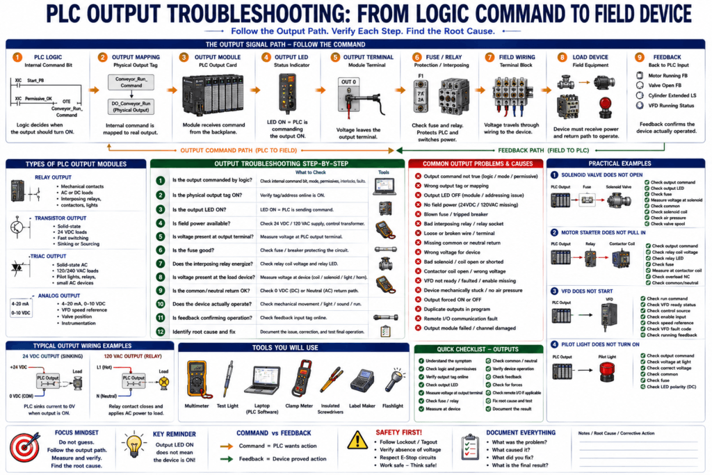
PLC output problems are very common in industrial automation.
A machine may have the correct input signals, the logic may look true online, but the real device still does not operate.
Examples:
The motor does not start.
The solenoid valve does not energize.
The pilot light does not turn ON.
The conveyor does not run.
The alarm horn does not sound.
The VFD does not receive a run command.
The cylinder does not extend.
The contactor does not pull in.
A PLC output is the command path from the controller to the real machine.
The important troubleshooting question is:
Is the PLC commanding the output, and is the field device actually receiving power?The Basic Rule
When troubleshooting PLC outputs, follow the output path.
PLC Logic
    ↓
Internal Command Bit
    ↓
Physical Output Tag / Address
    ↓
PLC Output Module
    ↓
Output LED
    ↓
Output Terminal
    ↓
Fuse / Relay / Terminal Block
    ↓
Field Wiring
    ↓
Load Device
    ↓
Feedback Signal
The goal is to find where the command stops.
Do not assume the output card is bad.
Do not assume the solenoid is bad.
Do not assume the PLC program is wrong.
Prove each step.
What Is a PLC Output Malfunction?
A PLC output malfunction happens when the machine does not respond correctly to a PLC command.
Examples:
PLC output bit is ON, but the device is OFF.
Output LED is ON, but no voltage reaches the load.
Voltage reaches the solenoid, but the valve does not shift.
Motor starter output is ON, but the contactor does not energize.
Contactor energizes, but motor does not run.
VFD run command is ON, but the drive does not start.
Output turns ON and OFF unexpectedly.
Output works in Manual Mode but not in Auto Mode.
Output problems can be caused by:
Program logic
Faults or interlocks
Output mapping
Output module failure
Missing field power
Blown fuse
Bad relay
Bad solenoid coil
Bad contactor coil
Broken wire
Missing common or neutral
Wrong voltage
Bad terminal connection
VFD not ready
Mechanical problem
Missing feedback
1. Start with the Symptom
First, define the problem clearly.
Bad symptom:
The machine is not working.Better symptom:
The conveyor motor does not start when Auto Start is pressed.Even better:
The PLC command bit turns ON, but the motor starter output does not energize.The better the symptom, the faster the troubleshooting.
2. Identify the Output Device
Before measuring anything, identify what output device is involved.
Common PLC output devices include:
Pilot lights
Stack lights
Alarm horns
Relays
Interposing relays
Solenoid valves
Motor starters
Contactors
VFD run commands
VFD speed references
Pneumatic valves
Hydraulic valves
Heater contactors
Brake release coils
Reject air solenoids
Then ask:
Is this output AC or DC?
Is it discrete or analog?
Is it local I/O or remote I/O?
Is it hardwired or networked?
Does it drive the device directly or through a relay?
Does it have feedback?
This helps you choose the correct troubleshooting path.
3. Understand Output Types
PLC output modules can be different types.
Common output types include:
Relay output
Transistor output
Triac output
Analog output
Network command output
Relay Output
A relay output uses an internal contact.
Common for:
AC loads
DC loads
Interposing relays
Small contactor coils
Pilot lights
Relay outputs are flexible, but they are mechanical and can wear over time.
Transistor Output
A transistor output is solid-state.
Common for:
24 VDC loads
Fast switching
Small DC solenoids
Relays
Pilot lights
Transistor outputs may be sinking or sourcing, so wiring polarity matters.
Triac Output
A triac output is solid-state and normally used for AC loads.
Common for:
120 VAC devices
AC pilot lights
AC relay coils
Small AC loads
Triac outputs can have leakage current, which can sometimes cause small loads to glow or behave strangely.
Analog Output
An analog output sends a variable signal.
Common signals:
4–20 mA
0–10 VDC
0–5 VDC
Used for:
VFD speed reference
Control valve position
Analog meter
Actuator position
Dosing command
This post focuses mainly on discrete outputs, but analog output troubleshooting follows the same principle: follow the signal.
4. Check If the PLC Logic Is Commanding the Output
Before checking voltage, go online with the PLC if safe and allowed.
Check:
Is the output command bit ON?
Is the machine in the correct mode?
Are permissives OK?
Are interlocks OK?
Is a fault blocking the output?
Is the sequence in the correct step?
Is the HMI command active?
Is the output mapped correctly?
Example:
Conveyor_Run_Command = ONIf the internal command bit is OFF, the problem may not be in the output circuit.
The problem may be:
Missing start request
Machine not in Auto
Stop active
Fault latched
Interlock active
Permissive missing
Wrong sequence step
VFD not ready
Safety not healthy
5. Check the Physical Output Tag or Address
A professional PLC program often separates internal command bits from physical outputs.
Example:
Internal command:
Conveyor_Run_Command

Physical output:
DO_Conveyor_Run
Or in hardware address format:
Local:2:O.Data.0
O:2/0
Make sure the internal command is actually mapped to the real output.
Example:
Conveyor_Run_Command → DO_Conveyor_RunPossible problem:
Command bit is ON,
but output mapping rung is missing or false.
This happens more often than people think.
6. Check the Output LED
Most PLC output modules have channel LEDs.
The output LED usually means:
The PLC is commanding that output channel ON.But very important:
Output LED ON does not always mean the field device is energized.The output LED may be ON, but the field circuit may still have a problem.
Possible causes:
No field power
Blown fuse
Bad relay contact
Loose terminal
Broken wire
Missing common or neutral
Bad solenoid coil
Bad contactor coil
Wrong voltage
So the output LED is a clue, not the final proof.
7. Check Field Power
Many PLC output modules need external field power.
The PLC module may have logic power, but the output load may need separate power.
Check:
24 VDC field power
120 VAC control power
Output group common
Output fuse
Output supply terminal
Load common / neutral
A very common problem is:
PLC output LED is ON,
but field power is missing.
Example:
Output card LED ON
No 24 VDC at output terminal
Fuse blown or no field supply
Solenoid OFF
8. Measure Voltage at the Output Terminal
Use a multimeter and measure at the PLC output terminal.
For a 24 VDC output:
Measure output terminal to 0 VDC common.For a 120 VAC output:
Measure output terminal to neutral.When the output is commanded ON, you should see the expected voltage.
Example:
24 VDC output ON → approximately 24 VDC at output terminal
120 VAC output ON → approximately 120 VAC at output terminal
If the output LED is ON but no voltage is present, check:
Output module field power
Output group common
Fuse
Module wiring
Bad output channel
Wrong terminal
9. Check the Fuse or Circuit Protection
Many output circuits are protected by fuses or breakers.
If a fuse is blown, the PLC output may be commanded ON, but the device will not energize.
Check:
Output fuse
Control fuse
Solenoid fuse
Relay fuse
Power supply fuse
Group fuse
Terminal block fuse holder
Do not only look at the fuse.
Verify with a meter.
A fuse can look good visually and still be open.
10. Check the Interposing Relay
Many PLC outputs do not drive field devices directly.
They drive an interposing relay.
Example:
PLC output → Interposing relay coil → Relay contact → Solenoid valveThis protects the PLC output module and allows control of different voltages or higher current loads.
If there is an interposing relay, check:
Does the relay coil energize?
Does the relay LED turn ON?
Is the relay socket tight?
Is the relay contact closing?
Is the correct voltage reaching the relay coil?
Is the relay contact passing voltage to the load?
Possible relay problems:
Bad relay coil
Bad relay contact
Loose relay socket
Wrong relay type
Wrong coil voltage
Burned contact
Relay not seated correctly
11. Check Voltage at the Load Device
If the output terminal is good, measure at the field device.
Example devices:
Solenoid connector
Contactor coil
Motor starter coil
Pilot light terminal
Horn terminal
VFD run input terminal
Valve actuator terminal
If voltage is present at the PLC output but not at the load, suspect:
Broken wire
Loose terminal
Bad relay contact
Bad fuse
Bad connector
Wrong terminal
Damaged cable
Corroded junction box
If voltage is present at the load but the load does not operate, suspect the load device or mechanical issue.
12. Check the Common, Neutral, or Return Path
A device needs a complete circuit.
A PLC output may send voltage to a device, but the device still needs a return path.
For DC:
+24 VDC supply path
Load
0 VDC common return
For AC:
Line / hot supply path
Load
Neutral return
Common problem:
Voltage is present on one side of the coil,
but the common or neutral is missing.
The device will not energize because the circuit is incomplete.
Always verify both sides of the load.
13. Check the Load Device
If voltage is correct at the load, check the device itself.
For a solenoid coil:
Check coil voltage rating.
Check coil resistance.
Check connector.
Check manual override.
Check valve spool.
Check air pressure.
For a contactor coil:
Check coil voltage rating.
Check A1/A2 terminals.
Check overload contact path.
Check mechanical movement.
Check auxiliary contact.
For a pilot light:
Check lamp voltage.
Check LED polarity if DC.
Check bulb/LED module.
Check common.
For a horn:
Check voltage.
Check common.
Check horn device.
Check silence circuit if used.
14. Check Command vs Feedback
Command and feedback are not the same.
Example:
PLC command:
DO_Motor_Start = ON

Feedback:
DI_Motor_Running_FB = ON
The output command only tells the device to operate.
Feedback proves that the device actually operated.
Examples:
| Device | Output Command | Feedback Input |
|---|---|---|
| Motor starter | DO_Motor_Starter | DI_Contactor_Aux |
| VFD | DO_VFD_Run_Command | DI_VFD_Running |
| Valve | DO_Valve_Open | DI_Valve_Open_FB |
| Cylinder | DO_Extend_Solenoid | DI_Extended_LS |
| Pump | DO_Pump_Run | DI_Pump_Running_FB |
If command is ON but feedback is missing, the PLC may generate a fault such as:
Motor Failed To Start
Valve Failed To Open
Cylinder Failed To Extend
This is professional troubleshooting logic.
15. Output Troubleshooting Examples
Example 1 — Solenoid Valve Does Not Energize
Symptom
PLC output LED is ON, but solenoid does not energize.Possible Causes
No field power
Blown fuse
Bad output channel
Loose terminal
Bad relay
Broken wire
Missing common
Wrong coil voltage
Bad solenoid coil
Valve mechanically stuck
No air pressure
Troubleshooting Path
1. Check output command online.
2. Check physical output tag.
3. Check output LED.
4. Measure voltage at output terminal.
5. Check fuse.
6. Check interposing relay.
7. Measure voltage at solenoid connector.
8. Check common.
9. Check solenoid coil.
10. Check valve manual override and air pressure.
Example 2 — Motor Starter Does Not Pull In
Symptom
PLC commands motor starter, but contactor does not energize.Possible Causes
Output not actually commanded
Overload contact open in control circuit
Blown control fuse
Bad starter coil
Wrong voltage
Loose A1/A2 wire
Bad interposing relay
Safety circuit open
Motor disconnect issue
Troubleshooting Path
1. Verify Motor_Run_Command.
2. Verify DO_Motor_Starter output.
3. Check output LED.
4. Measure control voltage at starter coil.
5. Check overload NC auxiliary contact.
6. Check safety permissive if in series.
7. Check starter coil resistance.
8. Check contactor mechanical movement.
9. Check auxiliary feedback.
Example 3 — VFD Does Not Start
Symptom
PLC run command is ON, but VFD does not run.Possible Causes
VFD not ready
VFD faulted
Drive in local mode instead of remote
Wrong control source
Run input not receiving signal
No drive enable
Safety input open
Network command not established
Parameter mismatch
Speed reference missing
Troubleshooting Path
1. Check VFD fault code.
2. Check VFD ready status.
3. Check PLC run command.
4. Check VFD control source.
5. Verify hardwired run input or network command.
6. Check speed reference.
7. Check enable/permissive terminals.
8. Check VFD running feedback.
Example 4 — Pilot Light Does Not Turn ON
Symptom
PLC output is ON, but pilot light is OFF.Possible Causes
Bad lamp
Wrong voltage
Missing common
Output fuse blown
Wrong output point
Bad LED polarity
Loose wire
No field power
Troubleshooting Path
1. Check PLC output LED.
2. Measure voltage at pilot light.
3. Check common.
4. Verify correct voltage rating.
5. Replace lamp module if voltage is correct.
6. Check output mapping if voltage is missing.
Example 5 — Output Turns ON Unexpectedly
Possible Causes
Output forced ON
Duplicate output coil
Wrong output mapping
Logic condition true unexpectedly
HMI command stuck ON
Internal bit latched
JMP/MCR logic confusing scan
Shorted output wiring
Relay contact welded
Output module failed ON
Troubleshooting Path
1. Check forces.
2. Search for duplicate output references.
3. Check command bit source.
4. Check HMI command tag.
5. Check latch/unlatch logic.
6. Check output mapping.
7. Disconnect load only if safe and authorized.
8. Check relay or output point.
16. Duplicate Outputs
A common PLC programming problem is writing to the same physical output in more than one place.
Example:
Rung 10 turns DO_Valve_Open ON.
Rung 45 turns DO_Valve_Open OFF.
The last scanned rung may win.
This creates confusing behavior.
Better structure:
Valve_Open_Request
Valve_Permissive_OK
Valve_Interlock_OK
Valve_Open_Command
DO_Valve_Open
Map the physical output only once.
Example:
Valve_Open_Command → DO_Valve_OpenThis is easier to troubleshoot.
17. Check for MCR, JMP, or Routine Not Scanned
Sometimes the output rung looks correct, but it is not being executed.
Check:
Is the routine being called by JSR?
Is the rung inside an MCR zone?
Is a JMP skipping the rung?
Is there a temporary end instruction?
Is the task running?
Is the module inhibited?
A rung cannot control an output if the PLC is not scanning it.
18. Check Remote I/O Outputs
If the output is on remote I/O, check communication.
Possible issues:
Remote adapter fault
Ethernet cable problem
Switch port fault
Remote rack power loss
Module inhibited
I/O connection fault
Wrong IP address
Electronic keying mismatch
Output module fault
A remote output can look correct in logic but fail physically if the remote I/O connection is broken.
19. Check for Output Module Failure
Output modules can fail, but prove it before replacing.
Possible signs:
Output LED ON but no voltage at output terminal
Only one point failed
Same group common/fuse affects multiple points
Module fault LED active
Output stuck ON
Output stuck OFF
Burn marks or odor
Known shorted load damaged point
Before replacing a module, check:
Field power
Fuse
Common
Wiring
Load current
Short circuit
Module status
Similar working output point
If a load shorted, replacing the output card without fixing the load can damage the new card.
20. Output Troubleshooting Decision Tree
Use this path:
1. Is the PLC logic commanding the output?
   No → troubleshoot permissives, interlocks, faults, mode, step.
   Yes → continue.

2. Is the physical output tag ON?
   No → troubleshoot output mapping.
   Yes → continue.

3. Is the output LED ON?
   No → check module status, address, force, configuration.
   Yes → continue.

4. Is voltage present at the output terminal?
   No → check field power, fuse, output group common, module point.
   Yes → continue.

5. Is voltage reaching the field device?
   No → check wiring, terminal block, relay, connector.
   Yes → continue.

6. Does the device operate?
   No → check coil, device voltage, common/neutral, mechanical issue.
   Yes → continue.

7. Does feedback confirm operation?
   No → troubleshoot feedback input path.
   Yes → output system is working.
Automation Technician Notes
For an Automation Technician, the most important output troubleshooting idea is:
An output command is not the same as device operation.The PLC can command an output, but the real device still needs:
Correct voltage
Complete circuit
Good fuse
Good relay
Good wiring
Correct common/neutral
Good coil/device
Mechanical ability to move
Feedback confirmation
A good technician follows the complete output path.
Output Troubleshooting Checklist
1. Identify the output device.
2. Confirm output voltage type.
3. Confirm output module type.
4. Check PLC command bit online.
5. Check physical output tag/address.
6. Check output mapping.
7. Check for permissives/interlocks/faults.
8. Check output LED.
9. Measure voltage at output terminal.
10. Check output fuse or breaker.
11. Check interposing relay.
12. Measure voltage at field device.
13. Check common/neutral return.
14. Check load coil or device.
15. Check mechanical movement.
16. Check feedback input.
17. Check for forces.
18. Check for duplicate outputs.
19. Check remote I/O status if applicable.
20. Document root cause.
Common Mistakes
1. Trusting the Output LED Only
Output LED ON does not prove the load is energized.
Always measure the field circuit.
2. Replacing the Output Module Too Fast
Many output problems are caused by:
Blown fuse
Missing field power
Bad relay
Loose terminal
Bad coil
Wrong common
Prove the module is bad before replacing it.
3. Ignoring the Return Path
A device needs both supply and return.
For DC, check 0 VDC common.
For AC, check neutral.
4. Confusing Command and Feedback
The output command may be ON, but the device may not have actually moved or started.
Always check feedback.
5. Forgetting VFD Ready Conditions
A VFD may receive a run command but refuse to run because it is faulted, not ready, in local mode, missing enable, or missing speed reference.
Good Output Tag Names
Good output names make troubleshooting easier.
Examples:
DO_Conveyor_Run
DO_Pump_Start
DO_Valve_Open
DO_Valve_Close
DO_Cylinder_Extend
DO_Cylinder_Retract
DO_Red_StackLight
DO_Green_StackLight
DO_Alarm_Horn
DO_VFD_Run_Command
AO_VFD_Speed_Reference
For internal commands:
Conveyor_Run_Command
Pump_Start_Command
Valve_Open_Command
Reject_Solenoid_Command
Best practice:
Internal Command → Physical OutputExample:
Reject_Solenoid_Command → DO_Reject_SolenoidKey Terms
| Term | Meaning |
|---|---|
| PLC Output | Signal commanded by the PLC to control a device |
| Output Module | PLC module that sends output signals |
| Output LED | Indicator showing output channel command status |
| Field Power | Power used to energize output loads |
| Interposing Relay | Relay between PLC output and field device |
| Load Device | Device controlled by the output |
| Common / Neutral | Return path for DC or AC circuit |
| Command | PLC request for a device to operate |
| Feedback | Input proving the device actually operated |
| Output Mapping | Final logic connecting command bits to physical outputs |
| Relay Output | Mechanical contact output type |
| Transistor Output | Solid-state DC output type |
| Triac Output | Solid-state AC output type |
| Duplicate Output | Same output written from multiple logic locations |
Final Thoughts
PLC output troubleshooting is about following the command from the program to the real device.
The PLC output path is:
Logic → Command → Output Module → Field Power → Load Device → FeedbackIf the device does not operate, find where the path breaks.
Is the logic commanding the output?
Is the physical output ON?
Is the output LED ON?
Is voltage leaving the module?
Is voltage reaching the device?
Is the common or neutral present?
Is the device mechanically working?
Does feedback confirm operation?
The professional mindset is:
Do not guess.
Follow the output path.
Measure voltage.
Confirm feedback.
Fix the root cause.