15. UDTs Explained: User-Defined Data Types for Industrial Devices
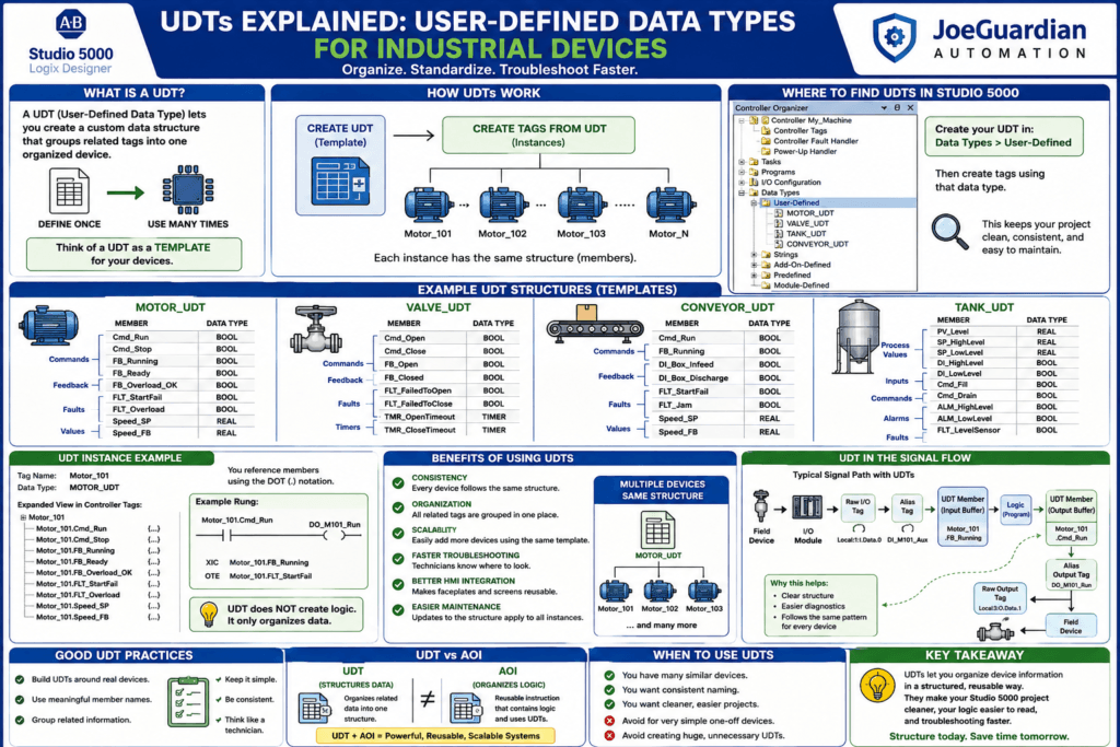
As Studio 5000 projects become larger, tag organization becomes increasingly important.
A small machine may only have a few motors, valves, sensors, and alarms. In that type of project, individual tags are easy to manage.
But imagine a machine with:
20 Motors
35 Valves
12 Conveyors
8 Tanks
40 Sensors
If every device uses separate individual tags, the project can quickly become difficult to organize.
This is where UDTs — User-Defined Data Types become extremely useful.
A UDT allows you to create a reusable data structure that groups all the information related to one type of device.
Instead of creating dozens of unrelated tags, you can organize them into a single structured device tag.
For example:
Motor_101could contain:
Motor_101.Cmd_Run
Motor_101.FB_Running
Motor_101.FLT_Overload
Motor_101.FLT_StartFail
Motor_101.Speed_SP
Motor_101.Speed_FB
That makes the PLC program more organized, scalable, and easier to troubleshoot.
What Is a UDT?
UDT stands for:
User-Defined Data TypeStudio 5000 already has built-in data types such as:
BOOL
DINT
REAL
TIMER
COUNTER
A UDT allows the programmer to create a custom data type.
For example, you could create:
MOTOR_UDTwith members such as:
Cmd_Run        BOOL
Cmd_Stop       BOOL
FB_Running     BOOL
FB_Ready       BOOL
FLT_Overload   BOOL
FLT_StartFail  BOOL
Speed_SP       REAL
Speed_FB       REAL
Then every motor can use the same structure.
Think of a UDT as a Device Template
A simple way to understand a UDT is to think of it as a template for data.
You design the template once.
Then you create many device tags from that template.
Conceptually:
MOTOR_UDT
     ↓
Motor_101
Motor_102
Motor_103
Motor_104
Each motor has the same internal structure.
For example:
Motor_101.Cmd_Run
Motor_102.Cmd_Run
Motor_103.Cmd_Run
Motor_104.Cmd_Run
This creates consistency throughout the project.
Why UDTs Matter in Industrial Projects
Industrial machines often contain many devices that behave similarly.
Examples:
- motors
- valves
- pumps
- conveyors
- tanks
- cylinders
- heaters
- VFDs
Without UDTs, programmers may create tags like:
M101_RunCmd
M101_RunFB
M101_OL
M101_StartFail
M101_SpeedSP

M102_RunCmd
M102_RunFB
M102_OL
M102_StartFail
M102_SpeedSP
This works, but the project can become messy.
With a UDT:
Motor_101.Cmd_Run
Motor_101.FB_Running
Motor_101.FLT_Overload
Motor_101.FLT_StartFail
Motor_101.Speed_SP
and:
Motor_102.Cmd_Run
Motor_102.FB_Running
Motor_102.FLT_Overload
Motor_102.FLT_StartFail
Motor_102.Speed_SP
The relationship between the tags becomes much clearer.
UDT Example — Industrial Motor
Let’s create a simple motor structure.
MOTOR_UDT
Cmd_Run        BOOL
Cmd_Stop       BOOL

FB_Running     BOOL
FB_Ready       BOOL
FB_Overload_OK BOOL

Permissive_OK  BOOL

FLT_StartFail  BOOL
FLT_Overload   BOOL

Speed_SP       REAL
Speed_FB       REAL
Now create:
Motor_101with data type:
MOTOR_UDTYou can now reference:
Motor_101.Cmd_Run
Motor_101.FB_Running
Motor_101.FLT_StartFail
Motor_101.Speed_SP
What Does the Dot Mean?
The dot tells Studio 5000 that you are accessing a member inside the structure.
Example:
Motor_101.FB_Runningmeans:
Motor_101
    ↓
FB_Running
Similarly:
Valve_201.FB_Openmeans:
Valve_201
    ↓
FB_Open
Once you become comfortable with structured tags, large Studio 5000 projects become much easier to read.
UDT Example — Pneumatic Valve
A valve may need several commands, feedbacks, and faults.
Create:
VALVE_UDTwith:
Cmd_Open
Cmd_Close

FB_Open
FB_Closed

Permissive_Open
Permissive_Close

FLT_FailedToOpen
FLT_FailedToClose

TMR_OpenTimeout
TMR_CloseTimeout
Then:
Valve_201
Valve_202
Valve_203
can all use the same structure.
For example:
Valve_201.Cmd_Open
Valve_201.FB_Open
Valve_201.FLT_FailedToOpen
UDT Example — Conveyor
A conveyor structure may include:
CONVEYOR_UDTwith:
Cmd_Run
FB_Running

DI_Box_Infeed
DI_Box_Discharge

Permissive_OK

FLT_StartFail
FLT_Jam
FLT_Overload

Speed_SP
Speed_FB
Then:
Conveyor_01
Conveyor_02
Conveyor_03
all follow the same organization.
UDT Example — Tank
UDTs are also useful for process equipment.
For example:
TANK_UDTcould contain:
PV_Level
SP_HighLevel
SP_LowLevel

DI_HighLevel
DI_LowLevel

Cmd_Fill
Cmd_Drain

FB_FillValveOpen
FB_DrainValveOpen

ALM_HighLevel
ALM_LowLevel

FLT_LevelSensor
Then create:
Tank_101
Tank_102
Tank_103
This gives every tank the same logical structure.
Why This Helps Technicians
For a technician, consistency is extremely valuable.
Imagine opening a large machine and finding:
Motor_201.FB_Running
Motor_202.FB_Running
Motor_203.FB_Running
You immediately understand where to look.
If Motor 201 has a start failure, you may inspect:
Motor_201.Cmd_Run
Motor_201.FB_Running
Motor_201.FB_Ready
Motor_201.FB_Overload_OK
Motor_201.FLT_StartFail
Everything related to the motor is grouped together.
That makes troubleshooting faster.
Compare This to Poor Tag Organization
Imagine instead that the tags are:
MTR201A
B_MTR201
M201_OK2
FLT201_3
RUN201_X
Even if the logic works, troubleshooting becomes harder because the naming structure is inconsistent.
UDTs encourage structured naming and repeatability.
UDTs Do Not Automatically Create Logic
This is extremely important.
A UDT organizes data.
It does not automatically control the motor, valve, or conveyor.
If you create:
Motor_101using:
MOTOR_UDTStudio 5000 does not automatically create:
- motor start logic
- fault logic
- permissive logic
- timer logic
- output logic
The UDT only creates the structured tags.
Think of it like this:
UDT = Data Structurenot:
UDT = Program LogicUDT vs AOI
This distinction becomes very important later in the series.
A UDT organizes data.
An AOI organizes reusable logic.
Conceptually:
UDT
=
Reusable Data Structure
while:
AOI
=
Reusable Logic Block
For example:
MOTOR_UDTmight contain all the motor data.
Then:
AOI_Motor_Controlcould process that data.
This combination can create very structured industrial programs.
We will explore AOIs later in this series.
UDTs and HMI Integration
UDTs can also make HMI development more organized.
Suppose every motor contains:
Cmd_Run
FB_Running
FLT_StartFail
FLT_Overload
The HMI can use a consistent tag structure.
For example:
Motor_101.FB_Running
Motor_101.FLT_Overload
and:
Motor_102.FB_Running
Motor_102.FLT_Overload
This makes it easier to create reusable HMI faceplates or device displays.
UDTs and Device Faceplates
In larger industrial systems, a motor may have an HMI faceplate showing:
Run Command
Running Feedback
Ready Status
Overload
Start Failure
Speed Setpoint
Speed Feedback
If all motors follow the same UDT structure, the HMI design becomes more predictable.
The same principle applies to:
- valves
- pumps
- conveyors
- tanks
- VFDs
Consistency between PLC and HMI is extremely valuable.
UDTs and Input Buffering
Remember our preferred signal flow:
Raw I/O
↓
Alias Tag
↓
Input Buffering
↓
Logic
↓
Output Buffering
↓
Field Device
A UDT can be used as part of that structure.
For example:
Motor_101.FB_Runningmay receive its value from:
DI_M101_Auxduring input processing.
Conceptually:
DI_M101_Aux
↓
Motor_101.FB_Running
Then the motor logic operates on the UDT member rather than directly on raw I/O.
This creates another layer of organization.
Example Input Buffering
You might have:
XIC    DI_M101_Aux
OTE    Motor_101.FB_Running
and:
XIC    DI_M101_OL_OK
OTE    Motor_101.FB_Overload_OK
Now the device structure contains the processed feedback.
Example Output Buffering
The motor logic may create:
Motor_101.Cmd_RunThen output buffering maps that command to the real output:
XIC    Motor_101.Cmd_Run
OTE    DO_M101_Run
The signal path becomes:
Field Input
↓
DI_M101_Aux
↓
Motor_101.FB_Running
↓
Motor Logic
↓
Motor_101.Cmd_Run
↓
DO_M101_Run
↓
Field Device
That is a very clean industrial structure.
UDTs and Arrays
UDTs become even more powerful when combined with arrays.
Suppose you have ten similar motors.
Instead of:
Motor_101
Motor_102
Motor_103
Motor_104
you could create an array such as:
Motor[0]
Motor[1]
Motor[2]
Motor[3]
where each element uses:
MOTOR_UDTThen:
Motor[0].Cmd_Run
Motor[0].FB_Running

Motor[1].Cmd_Run
Motor[1].FB_Running
This approach can be very powerful, especially in large modular systems.
However, arrays can sometimes make troubleshooting less intuitive if the device numbering is not documented well.
For technician-friendly projects, clarity should always come before clever programming.
UDTs Can Contain Other Data Types
UDT members are not limited to BOOL values.
You can include:
BOOL
DINT
REAL
TIMER
COUNTER
and other structures where appropriate.
For example:
VALVE_UDTmay contain:
Cmd_Open           BOOL
FB_Open            BOOL
FLT_OpenTimeout    BOOL
Open_Time_ms       DINT
Position_Percent   REAL
TMR_OpenTimeout    TIMER
This makes the structure very flexible.
Should Timers Be Inside the UDT?
This depends on programming philosophy.
Some programmers prefer:
Valve_101.TMR_OpenTimeoutwhile others keep timers separate:
TMR_Valve_101_OpenTimeoutBoth approaches can work.
The important thing is consistency.
For a technician-friendly project, ask:
Which structure makes the logic easiest to understand and troubleshoot?That should drive the decision.
UDT Member Naming
Because the parent tag already identifies the device, member names usually do not need to repeat it.
For example:
Good:
Motor_101.Cmd_Run
Motor_101.FB_Running
Motor_101.FLT_Overload
Less useful:
Motor_101.Motor_Run_Command
Motor_101.Motor_Running_Feedback
Motor_101.Motor_Overload_Fault
The second style contains unnecessary repetition.
Keep member names clean.
Follow the TRUE Naming Rule
The rule we established earlier still applies:
Name what TRUE means.Good examples:
FB_Ready
FB_Running
FB_Overload_OK
Permissive_OK
FLT_StartFail
ALM_HighLevel
Avoid ambiguous members like:
Overload
Door
Pressure
Fault1
Status
A technician should know what a TRUE bit means just by reading the name.
Example Motor UDT with Technician-Friendly Naming
MOTOR_UDT

Cmd_Run             BOOL
Cmd_Reset           BOOL

FB_Running          BOOL
FB_Ready            BOOL
FB_Overload_OK      BOOL

Permissive_OK       BOOL
Interlock_Active    BOOL

FLT_StartFail       BOOL
FLT_Overload        BOOL

ALM_NotReady        BOOL

Speed_SP            REAL
Speed_FB            REAL
This provides clear functional groups.
Think in Groups
A well-designed UDT often follows categories such as:
Commands
Feedback
Permissives
Interlocks
Faults
Alarms
Setpoints
Process Values
Status
For example:
Cmd_Run
Cmd_Reset

FB_Running
FB_Ready

Permissive_OK

FLT_StartFail
FLT_Overload

Speed_SP
Speed_FB
This mirrors good machine-control architecture.
Technician Troubleshooting Example
Suppose Motor 205 will not start.
Instead of searching randomly through the project, inspect:
Motor_205Expand the structure.
You may see:
Cmd_Run            = 1
FB_Ready           = 1
FB_Overload_OK     = 1
Permissive_OK      = 1
FB_Running         = 0
FLT_StartFail      = 1
This immediately tells you:
PLC wants motor ON
Ready is OK
Overload is OK
Permissives are OK
Running feedback is missing
Start failure is active
Now your field troubleshooting becomes much more focused.
Check:
Output
Contactor / VFD
Motor
Auxiliary feedback
Wiring
PLC input
That is the practical value of structured data.
Programmer Perspective
For programmers, UDTs provide:
- consistent device structures
- less naming chaos
- easier code reuse
- easier HMI integration
- cleaner projects
- easier expansion
If a machine later needs five more motors, you already have a standard structure.
You do not need to invent a new tag organization every time.
Standardization Is the Real Power
The biggest advantage of UDTs is not simply reducing the number of tag names.
The real advantage is standardization.
If every valve in the project follows:
Valve_xxx.Cmd_Open
Valve_xxx.Cmd_Close
Valve_xxx.FB_Open
Valve_xxx.FB_Closed
Valve_xxx.FLT_FailedToOpen
Valve_xxx.FLT_FailedToClose
then technicians learn the pattern once.
After that, they can troubleshoot any valve much faster.
UDTs and Large Projects
In a large ControlLogix project, you may see hundreds or thousands of tags.
Without organization, finding the correct signal can become difficult.
UDTs create hierarchy.
Instead of searching for:
MTR_217_Run_FByou can navigate:
Motor_217
    Cmd_Run
    FB_Running
    FB_Ready
    FLT_StartFail
The project becomes easier to explore.
When Should You Use a UDT?
UDTs are most useful when multiple devices share a common structure.
Good candidates:
Motors
Valves
Pumps
Conveyors
VFDs
Tanks
Cylinders
Heaters
Machine Stations
When a UDT May Be Unnecessary
Do not create a UDT for everything just because you can.
If a device only has:
One Input
One Output
and will never be repeated, creating a complex structure may add unnecessary complexity.
A UDT should improve organization, not make a simple project harder to understand.
Common UDT Mistakes
1. Creating Huge UDTs
Do not put every imaginable tag into one structure.
If a basic motor has 100 members, technicians may struggle to find what matters.
Build what the device actually needs.
2. Mixing Unrelated Data
A motor UDT should contain motor-related information.
Do not put unrelated machine status inside it.
3. Poor Member Names
Avoid:
Bit1
Bit2
Status1
Fault2
Value3
Use meaningful names.
4. Assuming UDTs Create Logic
Remember:
UDT = Datanot:
UDT = Logic5. Inconsistent UDT Usage
If half the motors use one structure and the other half use completely different naming, you lose much of the benefit.
Standardization matters.
UDT Troubleshooting Checklist
When troubleshooting a UDT-based device:
1. Find the device tag.

2. Expand the UDT members.

3. Check the command.

4. Check permissives.

5. Check interlocks.

6. Check field feedback.

7. Check faults and alarms.

8. Trace abnormal members back to their logic.

9. Trace the related I/O to the physical device.

10. Verify the device responds correctly after repair.
UDT + AOI — Where This Series Is Going
Later in this series, we will explore Add-On Instructions.
This is where things become especially powerful.
Imagine:
Motor_101using:
MOTOR_UDTand being processed by:
AOI_Motor_ControlConceptually:
Field I/O
↓
Motor UDT
↓
Motor AOI
↓
Commands / Feedback / Faults
↓
HMI
Now the PLC project begins to look like a library of standardized industrial devices.
This is a major step from basic ladder programming toward professional, reusable control architecture.
Key Terms
UDT = User-Defined Data Type

Member = Individual item inside a UDT

Structure = Group of related data

Instance = A tag created using a UDT

Array = Multiple elements of the same data type

AOI = Add-On Instruction

Standardization = Using the same structure consistently across similar devices
Final Thoughts
UDTs are one of the most important organizational tools in Studio 5000.
They allow programmers to group related device information into clean, reusable structures.
Instead of scattered tags:
M101_Run
M101_FB
M101_OL
M101_Fault
you can create:
Motor_101.Cmd_Run
Motor_101.FB_Running
Motor_101.FB_Overload_OK
Motor_101.FLT_StartFail
For programmers, this improves standardization and scalability.
For technicians, it creates predictable troubleshooting.
Once you understand the pattern of one device, you can often understand every similar device in the project.
The key idea is simple:
UDT = Organize related device data into one reusable structure.And remember:
UDT organizes the data.
AOI will eventually organize the reusable logic.
Understanding that difference prepares us for the more advanced Studio 5000 programming concepts ahead.