6. Sinking and Sourcing Inputs Explained Simply ( 6 of 35 )
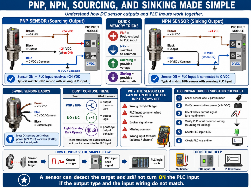
One of the most confusing topics for many automation technicians is sinking and sourcing.
You may hear people say:
PNP sensor
NPN sensor
Sourcing input
Sinking input
Current sourcing
Current sinking
At first, it sounds complicated. But the basic idea is simple:
Sourcing = provides positive voltage/current
Sinking = provides the path back to negative/common
In PLC input circuits, sinking and sourcing describe the direction of current flow between the field device and the PLC input module.
According to Programmable Logic Controllers, 6th Edition, sinking and sourcing terminology applies to DC input and output circuits. A sourcing device provides current when it is ON, while a sinking device receives current when it is ON. The book also explains that a sourcing I/O device or module is connected to the positive side of the DC supply, while a sinking device or module is connected to the negative side.
Why This Matters
If the PLC input module and the sensor are not compatible, the input may never turn ON.
This is a very common real-world troubleshooting issue.
Example:
Sensor LED turns ON
But PLC input LED stays OFF
Possible cause:
PNP/NPN mismatch
Sinking/sourcing mismatch
Missing common
Wrong wiring
Wrong input module type
Understanding sinking and sourcing helps you troubleshoot 24 VDC sensor circuits faster.
The Basic Rule
The easiest way to remember it:
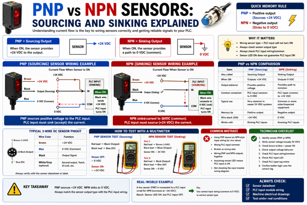
PNP sensor = sourcing sensor = sends +24 VDC to the PLC input
NPN sensor = sinking sensor = pulls the PLC input to 0 VDC/common
Another simple rule:
PNP switches the positive side.
NPN switches the negative side.
What Is a Sourcing Device?
A sourcing device provides positive voltage/current to the circuit.
In most industrial 24 VDC sensor circuits:
Sourcing device = sends +24 VDC when ONExample:
PNP proximity sensor turns ON
        ↓
Sensor output sends +24 VDC
        ↓
PLC input receives positive voltage
        ↓
PLC input turns ON
So when people say PNP sensor, they usually mean:
The sensor sources positive voltage to the PLC input.What Is a Sinking Device?
A sinking device provides the return path to 0 VDC/common.
In a sinking circuit:
The load or input receives positive voltage from one side.
The sinking device completes the path to 0 VDC.
Example:
NPN proximity sensor turns ON
        ↓
Sensor output connects the PLC input to 0 VDC/common
        ↓
Current flows through the input circuit
        ↓
PLC input turns ON
So when people say NPN sensor, they usually mean:
The sensor sinks current back to common.PNP vs NPN Sensors
PNP Sensor
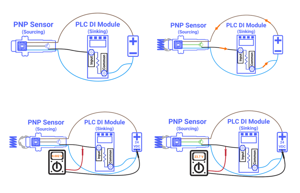
A PNP sensor is usually a sourcing sensor.
When the sensor detects the target, the output wire provides +24 VDC.
Brown wire  = +24 VDC
Blue wire   = 0 VDC
Black wire  = Output signal
When ON:
Black wire outputs +24 VDCCommon description:
PNP = Positive switching
PNP = Sourcing output
NPN Sensor
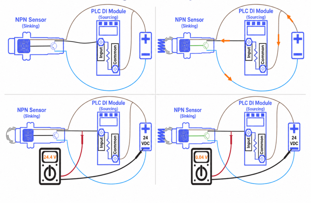
An NPN sensor is usually a sinking sensor.
When the sensor detects the target, the output wire connects to 0 VDC/common.
Brown wire  = +24 VDC
Blue wire   = 0 VDC
Black wire  = Output signal
When ON:
Black wire switches to 0 VDC/commonCommon description:
NPN = Negative switching
NPN = Sinking output
Simple Comparison
| Sensor Type | Common Name | What It Switches | Output When ON | Easy Memory Rule |
|---|---|---|---|---|
| PNP | Sourcing sensor | Positive side | +24 VDC | PNP = Positive |
| NPN | Sinking sensor | Negative side | 0 VDC/common | NPN = Negative |
PLC Input Modules: Sinking vs Sourcing
This is where many technicians get confused.
A sensor and a PLC input module must be electrically compatible.
The relationship is usually:
Sourcing sensor connects to sinking input module.
Sinking sensor connects to sourcing input module.
Why?
Because current needs a complete path:
+24 VDC → load/input circuit → 0 VDCOne side must provide current, and the other side must receive/sink it.
PNP Sensor with Sinking PLC Input
This is one of the most common industrial wiring styles.
PNP sensor = sourcing device
PLC input module = sinking input
When the sensor turns ON:
Sensor sends +24 VDC to PLC input
PLC input accepts current and returns it to common
Input LED turns ON
PLC input bit becomes 1
Basic concept:
+24 VDC → PNP sensor output → PLC input → commonNPN Sensor with Sourcing PLC Input
This is also used, but it is less common in many modern U.S. industrial panels.
NPN sensor = sinking device
PLC input module = sourcing input
When the sensor turns ON:
PLC input provides current
NPN sensor completes path to 0 VDC
Input LED turns ON
PLC input bit becomes 1
Basic concept:
+24 VDC → PLC input → NPN sensor output → commonEasy Visual Concept
Think about current like water flow.
Sourcing = sends current out
Sinking = receives current back
A working circuit needs both:
Source side + Sink side = complete current path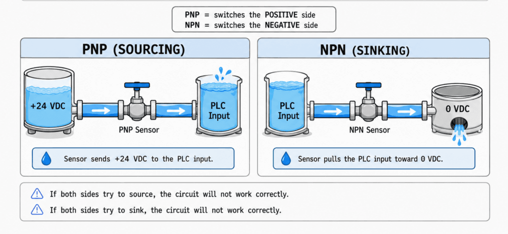
Typical 3-Wire DC Sensor Wiring
Most 3-wire DC sensors use this color code:
| Wire Color | Function |
|---|---|
| Brown | +24 VDC |
| Blue | 0 VDC / DC common |
| Black | Output signal |
| White | Second output, if available |
For many sensors:
Brown = positive power
Blue = negative/common
Black = signal to PLC input
Important:
Always verify the sensor datasheet. Wire colors are common, but never assume blindly.
PNP Sensor Wiring Example
PNP / Sourcing Sensor
Brown → +24 VDC
Blue  → 0 VDC
Black → PLC input terminal
PLC input common → 0 VDC
When target is detected:
Black wire = +24 VDC
PLC input turns ON
Troubleshooting check:
Measure black wire to blue/common.
Target absent  = usually 0 VDC
Target present = usually +24 VDC
NPN Sensor Wiring Example
NPN / Sinking Sensor
Brown → +24 VDC
Blue  → 0 VDC
Black → PLC input terminal
PLC input common → +24 VDC
When target is detected:
Black wire is pulled to 0 VDC
PLC input turns ON
Troubleshooting check:
Measure black wire to blue/common.
Behavior depends on circuit design.
You may see the signal pulled low when active.
For NPN circuits, you must be more careful with where you place the meter leads because the input module may be providing the positive side.
The Most Important Troubleshooting Point
A sensor LED turning ON does not always mean the PLC input will turn ON.
The sensor may be powered and detecting, but the output may not be wired correctly for the PLC input module.
Example:
Sensor has power
Sensor detects target
Sensor LED turns ON
PLC input LED stays OFF
Possible causes:
Wrong sensor type: PNP vs NPN
Wrong input module type
Missing input common
Broken signal wire
Wrong terminal
Incorrect sensor output wire
Bad sensor output
Bad PLC input point
How to Troubleshoot a PNP Sensor Input
For a typical PNP sensor connected to a sinking PLC input:
Step 1 — Check Sensor Power
Measure:
Brown to Blue = approximately 24 VDCIf no voltage:
Check power supply
Check fuse
Check terminal block
Check cable
Step 2 — Check Sensor Output
Measure:
Black to Blue/commonWhen target is not detected:
Output should usually be OFFWhen target is detected:
Output should go to approximately +24 VDCStep 3 — Check PLC Input Terminal
Measure at the PLC input terminal:
Input terminal to commonWhen sensor is ON:
You should see approximately +24 VDCIf you have voltage at the sensor but not at the PLC input:
Check cable
Check terminal block
Check wiring
Check input point
Step 4 — Check Input LED
If +24 VDC is present at the input terminal but the input LED is OFF:
Check module common
Check input module type
Check input threshold
Check input module health
Check wiring reference
Step 5 — Check PLC Tag
If the input LED is ON but the PLC tag is not changing:
Check correct input address
Check alias tag
Check program mapping
Check module configuration
Check online connection
How to Troubleshoot an NPN Sensor Input
For an NPN sensor, the troubleshooting method depends on the module wiring.
General checks:
Verify sensor power: Brown to Blue = 24 VDC
Verify sensor type from label or datasheet
Verify PLC input common wiring
Check whether input module is sourcing type
Check black signal wire behavior when sensor turns ON
Check PLC input LED
Check PLC input tag
Important:
Do not troubleshoot NPN the same way as PNP without understanding the input common wiring.
With NPN, the sensor is usually pulling the signal low, not sending +24 VDC out.
Common Mistake 1 — Replacing the Sensor Too Fast
Sometimes the sensor is not the problem.
Example:
Sensor LED turns ON
Sensor output changes
But PLC input does not turn ON
The actual problem may be:
Missing common
Wrong PNP/NPN type
Broken wire
Wrong input module type
Bad terminal connection
Before replacing the sensor, measure the circuit.
Common Mistake 2 — Confusing Sensor Output with Sensor Power
A 3-wire sensor has power wires and an output wire.
Brown and blue power the sensor.
Black sends the signal to the PLC.
A sensor can have correct power but still have no output signal.
Or the sensor output can be working but not reaching the PLC input.
Always check:
Power side
Signal side
PLC input side
Common Mistake 3 — Not Checking the Input Common
The input common is critical.
Without the correct common, the input circuit cannot complete the path.
Symptoms:
No input LEDs turn ON
Only some inputs work
Sensor outputs measure correctly but PLC does not see them
Input card appears dead
Signals behave inconsistently
Check:
Input module common terminal
24 VDC common reference
Jumper wiring
Terminal block wiring
Module group commons
Some input modules have groups of commons, so one common may feed only a section of the module.
Common Mistake 4 — Mixing PNP and NPN Devices
Some machines have mixed sensor types because of replacement parts, old modifications, or imported equipment.
Example:
Original sensor = PNP
Replacement sensor = NPN
Result:
Sensor physically fits
Connector may fit
Sensor LED may turn ON
PLC input does not work
Always verify:
Sensor part number
PNP/NPN output type
Normally Open or Normally Closed output
Connector pinout
PLC input module type
Normally Open vs Normally Closed Sensor Output
PNP and NPN describe the electrical output type.
NO and NC describe the switching behavior.
They are not the same thing.
Example sensor options:
PNP Normally Open
PNP Normally Closed
NPN Normally Open
NPN Normally Closed
A PNP NO sensor sends +24 VDC when it detects the target.
A PNP NC sensor sends +24 VDC when it does not detect the target.
So when replacing sensors, check both:
PNP or NPN
NO or NC
Practical Example: Photoeye Not Seen by PLC
Situation
A conveyor photoeye detects a box. The sensor light turns ON, but the PLC input stays OFF.
Possible Causes
Wrong sensor type installed
PNP sensor connected to sourcing input
NPN sensor connected to sinking input
Missing DC common
Signal wire landed on wrong terminal
Broken wire between sensor and PLC
Input module common not connected
Input point failed
PLC program looking at wrong tag
Best Troubleshooting Path
1. Check sensor power.
2. Confirm PNP or NPN sensor type.
3. Measure sensor output wire.
4. Verify PLC input module common.
5. Measure voltage at PLC input terminal.
6. Check input LED.
7. Check PLC tag online.
8. Compare wiring to electrical drawing.
Practical Example: Proximity Sensor Replacement
Problem
A proximity sensor was replaced, but the PLC no longer sees the part.
What to Check
Is the new sensor the same voltage?
Is it PNP or NPN?
Is it NO or NC?
Is the connector pinout the same?
Is the sensing distance correct?
Is the target material correct?
Is the sensor output wired to the correct input?
Does the input LED turn ON?
Many “bad new sensor” problems are actually wrong sensor specification problems.
PNP/NPN Quick Field Test
For a typical 3-wire sensor:
Check Power
Brown to Blue = 24 VDCCheck Output Type
With the sensor connected and switching:
Black to Blue/commonIf black goes to +24 VDC when active:
Likely PNP / sourcing outputIf black pulls low or completes to common when active:
Likely NPN / sinking outputImportant:
This is a field test concept, not a replacement for reading the datasheet.
Always verify the part number.
Sinking and Sourcing in Outputs
This post focuses mainly on inputs, but the same concept also applies to DC outputs.
A PLC output module may be:
Sourcing output module
Sinking output module
Sourcing Output Module
Output sends +24 VDC to the load
Load returns to 0 VDC
Common with:
24 VDC solenoids
Relays
Pilot lights
Small DC loads
Sinking Output Module
Load receives +24 VDC
PLC output completes the path to 0 VDC
Again, the output module and field device wiring must match.
Simple Memory Trick
Use this:
PNP = Positive
NPN = Negative
More complete version:
PNP sources positive voltage to the input.
NPN sinks current to negative/common.
And:
A sourcing device needs a sinking input.
A sinking device needs a sourcing input.
Automation Technician Notes
When troubleshooting 24 VDC PLC inputs, always ask:
Is this a PNP or NPN sensor?
Is the PLC input module sinking or sourcing?
Is the input common wired correctly?
Is the sensor output NO or NC?
Is the sensor powered?
Is the sensor output changing?
Is the PLC input LED changing?
Is the PLC tag changing?
Do not troubleshoot only by looking at the sensor LED.
A sensor LED tells you the sensor is detecting.
It does not always prove the PLC is receiving the correct electrical signal.
Field Troubleshooting Checklist
Use this checklist when a DC sensor input is not working:
1. Confirm sensor voltage rating.
2. Confirm sensor type: PNP or NPN.
3. Confirm output state: NO or NC.
4. Check brown to blue for 24 VDC.
5. Check black output wire while triggering sensor.
6. Verify signal reaches PLC input terminal.
7. Check PLC input common wiring.
8. Check input LED.
9. Check PLC tag online.
10. Confirm program uses the correct tag.
11. Check for input filtering or debounce.
12. Check electrical drawings.
This method will save a lot of time.
Key Terms
| Term | Meaning |
|---|---|
| Sourcing | Provides positive voltage/current |
| Sinking | Provides return path to 0 VDC/common |
| PNP | Common sourcing sensor type |
| NPN | Common sinking sensor type |
| Input Module | PLC module that receives field signals |
| Input Common | Common reference needed to complete input circuit |
| 24 VDC | Common industrial control voltage |
| NO | Normally Open |
| NC | Normally Closed |
| Sensor Output | Signal wire from sensor to PLC input |
| DC Common | 0 VDC reference |
| Input LED | Indicator showing input module sees signal |
| Field Device | Physical sensor or switch connected to PLC |
Final Thoughts
Sinking and sourcing are essential concepts for understanding DC PLC input circuits.
The simplest way to remember them is:
PNP sources positive voltage.
NPN sinks current to common.
A PLC input circuit must have a complete current path. That means the sensor type, PLC input module type, power supply, common, and wiring must all match.
For an Automation Technician, understanding sinking and sourcing makes sensor troubleshooting much easier. It helps you quickly identify whether the problem is the sensor, wiring, common, input module, or logic.
Once this concept becomes clear, PNP/NPN wiring becomes much less intimidating.