5. Discrete I/O vs Analog I/O ( 5 of 35 )
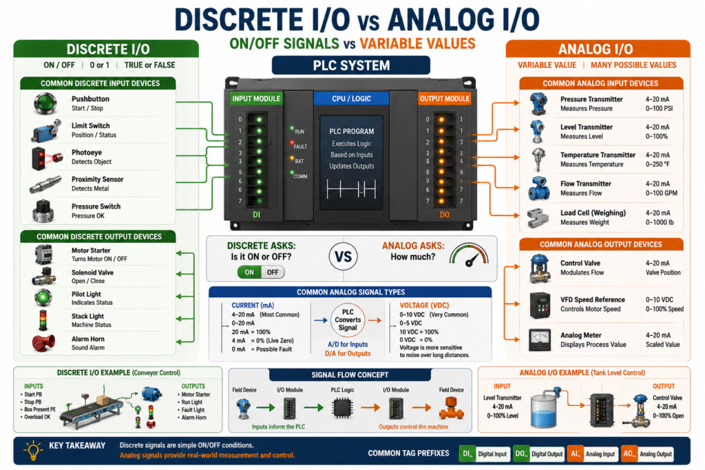
In PLC systems, not all signals are the same.
Some signals are simple ON/OFF signals. Other signals represent a changing value such as pressure, temperature, tank level, speed, or weight.
That is why PLC input and output signals are commonly divided into two major categories:
Discrete I/O
Analog I/O
A simple way to understand the difference is:
Discrete = ON or OFF
Analog = Variable value
According to Programmable Logic Controllers, 6th Edition, discrete I/O modules are used for ON/OFF devices such as pushbuttons, limit switches, lights, relays, solenoids, and motor starters, while analog I/O modules are used when the control process requires continuously variable signals such as temperature, level, flow, weight, pressure, speed, or position.
What Is Discrete I/O?
Discrete I/O is used for signals that have only two possible states.
ON / OFF
TRUE / FALSE
1 / 0
Energized / De-energized
Made / Not Made
In PLC logic, discrete signals are usually handled as BOOL tags or individual bits.
Example:
DI_Start_PB = 1
DI_Stop_OK = 1
DI_Box_Present = 0
DO_Motor_Run = 1
This means the signal is either active or inactive.
Discrete Input Examples
Discrete inputs tell the PLC whether something is ON or OFF.
Common discrete input devices include:
Pushbuttons
Selector switches
Limit switches
Proximity sensors
Photoelectric sensors
Pressure switches
Level switches
Flow switches
Motor overload auxiliary contacts
VFD fault contacts
Safety relay feedback contacts
Example:
A box passes in front of a photoeye.
The photoeye output turns ON.
The PLC input bit becomes 1.
In simple logic:
IF Box_Present = ON
THEN Stop Conveyor
Discrete Output Examples
Discrete outputs allow the PLC to turn devices ON or OFF.
Common discrete output devices include:
Pilot lights
Stack lights
Relays
Interposing relays
Solenoid valves
Motor starters
Contactors
Alarm horns
VFD start commands
Heater contactors
Example:
PLC output turns ON.
The solenoid valve energizes.
The pneumatic cylinder extends.
In simple logic:
IF Valve_Command = ON
THEN Energize Solenoid
Discrete I/O in Real Machines
Discrete I/O is very common in machine control.
Example: Conveyor control
Inputs
Start Pushbutton
Stop Pushbutton
Box Present Photoeye
Motor Overload OK
Emergency Stop OK
Outputs
Motor Starter
Run Light
Fault Light
Alarm Horn
The PLC logic may look like this in plain English:
If Start is pressed
AND Stop is OK
AND Overload is OK
AND E-Stop is OK
THEN run the conveyor motor.
That entire decision is based mostly on discrete signals.
What Is Analog I/O?
Analog I/O is used for signals that represent a changing value.
Instead of only ON or OFF, analog signals can represent many values within a range.
Examples:
Tank level = 62%
Pressure = 85 PSI
Temperature = 145°F
Flow = 32 GPM
Weight = 450 lb
Speed = 38 Hz
Position = 12.5 inches
Analog signals are commonly used in process control, instrumentation, VFD speed control, tank systems, filling machines, heating systems, weighing systems, and PID control.
Common Analog Signal Types
Common analog signal ranges include:
4–20 mA
0–20 mA
0–10 VDC
0–5 VDC
-10 to +10 VDC
The most common industrial analog signal is usually:
4–20 mAThis is widely used because it is reliable for industrial environments and better for longer cable runs than voltage signals.
Analog Input Examples
Analog inputs bring variable process values into the PLC.
Common analog input devices include:
Pressure transmitters
Level transmitters
Temperature transmitters
Flow transmitters
Load cells through a scale module or transmitter
pH transmitters
Conductivity transmitters
Ultrasonic distance sensors
Potentiometers
VFD speed feedback signals
Example:
A pressure transmitter measures 0–100 PSI.
The transmitter sends 4–20 mA to the PLC.
The PLC converts that signal into a pressure value.
Simple scaling idea:
4 mA  = 0 PSI
20 mA = 100 PSI
12 mA = 50 PSI
Analog Output Examples
Analog outputs send variable commands from the PLC to field devices.
Common analog output devices include:
Control valves
VFD speed references
Positioners
Analog meters
Process controllers
Actuators
Dosing systems
Example:
PLC sends 4–20 mA to a control valve.
4 mA = valve closed
20 mA = valve fully open
Another example:
PLC sends 0–10 VDC to a VFD.
0 VDC = 0% speed
10 VDC = 100% speed
Discrete vs Analog: Simple Comparison
| Feature | Discrete I/O | Analog I/O |
|---|---|---|
| Signal type | ON/OFF | Variable value |
| PLC data type | BOOL / bit | INT, DINT, REAL |
| Common input devices | Pushbuttons, sensors, switches | Transmitters, probes, analog sensors |
| Common output devices | Relays, solenoids, lights, starters | VFD speed reference, control valve |
| Example value | 0 or 1 | 0–100 PSI, 4–20 mA, 0–10 V |
| Troubleshooting focus | Voltage present or not present | Signal value, scaling, wiring, noise |
| Typical use | Machine status and commands | Process measurement and control |
Easy Way to Remember
Use this simple rule:
Discrete tells the PLC: Is it ON or OFF?
Analog tells the PLC: How much?
Examples:
Discrete: Is the tank high level switch ON?
Analog: What percentage full is the tank?
Discrete: Is the pressure switch made?
Analog: What is the actual pressure in PSI?Discrete: Is the motor running?
Analog: What speed is the motor running?Practical Example: Tank Level
A tank can use either discrete or analog level detection.
Discrete Level Switch
Low Level Switch = ON/OFF
High Level Switch = ON/OFF
This tells the PLC only whether the level has reached a specific point.
Example:
High_Level_Switch = ON
Stop filling tank
Analog Level Transmitter
Level_Transmitter = 4–20 mA
PLC displays Tank_Level_Percent = 0–100%
This tells the PLC the actual level value.
Example:
Tank_Level = 68%
Continue filling until 90%
Both methods are useful, but they provide different information.
Practical Example: Motor Control
A motor system may use both discrete and analog signals.
Discrete Signals
Start Command
Stop Command
VFD Fault
VFD Running
Motor Overload OK
Analog Signals
Speed Reference
Speed Feedback
Motor Current
Process Pressure
Flow Rate
Example:
Discrete output starts the VFD.
Analog output tells the VFD what speed to run.
Analog input may read motor current or process pressure.
This is common in real industrial systems.
Practical Example: Pressure Control
A pressure switch and a pressure transmitter are not the same thing.
Pressure Switch
A pressure switch is usually discrete.
Pressure_OK = ON
Pressure_Low = OFF
It changes state at a set pressure point.
Example:
Pressure switch closes at 60 PSI.
PLC sees input ON.
Pressure Transmitter
A pressure transmitter is analog.
Pressure = 0–100 PSI
Signal = 4–20 mA
It sends the actual pressure value to the PLC.
Example:
PLC reads 12 mA.
Scaled pressure = 50 PSI.
How the PLC Reads Analog Signals
The PLC cannot directly “understand” a raw analog signal the same way a meter displays it.
An analog input module converts the analog signal into a digital value the PLC processor can use.
This process is called:
Analog-to-Digital Conversion
A/D Conversion
Example:
4–20 mA signal
        ↓
Analog Input Module
        ↓
Raw Digital Value
        ↓
PLC Scaling Logic
        ↓
Engineering Units
Final result:
Raw value → 72.5 PSIHow the PLC Sends Analog Outputs
For analog outputs, the PLC does the opposite.
The PLC starts with a digital command value and the analog output module converts it into a physical current or voltage signal.
This is called:
Digital-to-Analog Conversion
D/A Conversion
Example:
PLC Speed Command = 50%
        ↓
Analog Output Module
        ↓
5 VDC signal to VFD
        ↓
VFD runs at 50% speed
Or:
PLC Valve Command = 75%
        ↓
Analog Output Module
        ↓
16 mA signal
        ↓
Valve opens to 75%
Understanding 4–20 mA
The 4–20 mA signal is one of the most common analog signals in industry.
A typical example:
4 mA  = 0%
20 mA = 100%
For a pressure transmitter:
4 mA  = 0 PSI
20 mA = 100 PSI
For a tank level transmitter:
4 mA  = Empty
20 mA = Full
For a valve command:
4 mA  = Closed
20 mA = Open
Why Not 0–20 mA?
A major advantage of 4–20 mA is that 4 mA represents the live zero.
That means:
4 mA = valid zero measurement
0 mA = possible fault, broken wire, or lost power
Example:
Tank level transmitter reads 4 mA
PLC interprets tank as 0%
But:
Tank level transmitter reads 0 mA
PLC may interpret signal failure
This makes 4–20 mA very useful for diagnostics.
Analog Scaling
Analog scaling converts a raw PLC value into engineering units.
Engineering units are values humans understand.
Examples:
PSI
GPM
°F
°C
%
Gallons
RPM
Inches
Pounds
Example:
Raw analog input = 16384
Scaled pressure = 50 PSI
A simple concept:
Raw Signal → Scaling → Engineering ValueFor example:
4–20 mA → 0–100 PSIThe PLC program or module configuration converts the raw signal into a useful pressure value.
Discrete I/O Troubleshooting
Discrete I/O troubleshooting is usually about checking ON/OFF status.
For Discrete Inputs
Check:
Is the sensor powered?
Is the sensor switching?
Is the input LED turning ON?
Is 24 VDC present at the input terminal?
Is the input common correct?
Is the PLC tag changing state?
Is the logic using the correct tag?
For Discrete Outputs
Check:
Is the output command ON?
Is the output LED ON?
Is field power present?
Is the fuse good?
Is the relay or solenoid coil good?
Is the correct voltage reaching the load?
Is the device mechanically working?
Analog I/O Troubleshooting
Analog troubleshooting is different because you are not only checking ON/OFF.
You are checking whether the value makes sense.
For Analog Inputs
Check:
Is the transmitter powered?
Is the loop wiring correct?
Is the signal 4–20 mA or 0–10 V?
Is the PLC channel configured correctly?
Is the raw value changing?
Is the scaling correct?
Is the engineering unit value realistic?
Is the shield grounded correctly?
Is electrical noise affecting the signal?
For Analog Outputs
Check:
Is the PLC sending the correct command?
Is the analog output channel enabled?
Is the output configured for current or voltage?
Is the field device wired correctly?
Is the valve or VFD receiving the signal?
Is the receiving device scaled/configured correctly?
Common Mistake: Confusing Switches and Transmitters
A common beginner mistake is confusing a switch with a transmitter.
Switch
A switch is usually discrete.
Pressure switch = ON/OFF
Level switch = ON/OFF
Flow switch = ON/OFF
Transmitter
A transmitter is usually analog.
Pressure transmitter = actual pressure value
Level transmitter = actual level value
Flow transmitter = actual flow value
Simple rule:
Switch = Has it reached the setpoint?
Transmitter = What is the actual value?
Common Mistake: Thinking Analog Is Always More Accurate
Analog gives more information, but it is not always the best choice.
Sometimes a discrete switch is enough.
Example:
If you only need to know “tank full,” use a level switch.
If you need to know the exact tank percentage, use a level transmitter.
The correct device depends on the control requirement.
Automation Technician Notes
When you see a PLC signal, always ask:
Is this signal discrete or analog?
Is it an input or output?
Is it a command or feedback?
Is it a field device or internal tag?
Is the PLC reading raw counts or engineering units?
Is the value realistic for the process?
This helps you understand the system faster.
A strong technician does not only look at whether a tag is ON or OFF. A strong technician understands what type of signal it is, where it comes from, and what it means in the machine.
Real Troubleshooting Example
Problem
An HMI shows tank level stuck at 0%.
Possible Causes
Transmitter has no power
Broken 4–20 mA loop
Analog input channel failed
Wrong channel configuration
Bad scaling
Open wire causing 0 mA
Shield/noise issue
Transmitter failure
PLC tag not mapped correctly
HMI reading wrong tag
Better Troubleshooting Path
1. Check transmitter power.
2. Measure loop current with meter.
3. Verify 4–20 mA signal.
4. Check PLC analog input raw value.
5. Verify scaling.
6. Compare PLC value with HMI value.
7. Check wiring and shield.
8. Confirm transmitter range.
This is the difference between replacing parts and troubleshooting properly.
Key Terms
| Term | Meaning |
|---|---|
| Discrete I/O | ON/OFF PLC signals |
| Analog I/O | Variable PLC signals |
| Digital Input | ON/OFF input from a field device |
| Digital Output | ON/OFF command to a field device |
| Analog Input | Variable signal coming into the PLC |
| Analog Output | Variable signal sent from the PLC |
| 4–20 mA | Common industrial analog current signal |
| 0–10 VDC | Common analog voltage signal |
| A/D Conversion | Analog-to-digital conversion |
| D/A Conversion | Digital-to-analog conversion |
| Scaling | Converting raw values into engineering units |
| Engineering Units | Human-readable units such as PSI, GPM, °F, % |
| Transmitter | Device that sends analog process value |
| Switch | Device that changes ON/OFF state |
Final Thoughts
Understanding the difference between discrete I/O and analog I/O is essential for PLC troubleshooting.
Discrete signals answer simple ON/OFF questions:
Is the sensor ON?
Is the motor running?
Is the valve open?
Analog signals answer value-based questions:
How much pressure?
What tank level?
What temperature?
What speed?
For an Automation Technician, this distinction is critical. It helps you know what to measure, what to expect, how to read the PLC tag, and how to troubleshoot the circuit correctly.
Once you understand discrete and analog I/O, PLC systems become much easier to read, diagnose, and control.