34. How to Read and Understand an Existing PLC Program ( 34 of 35 )
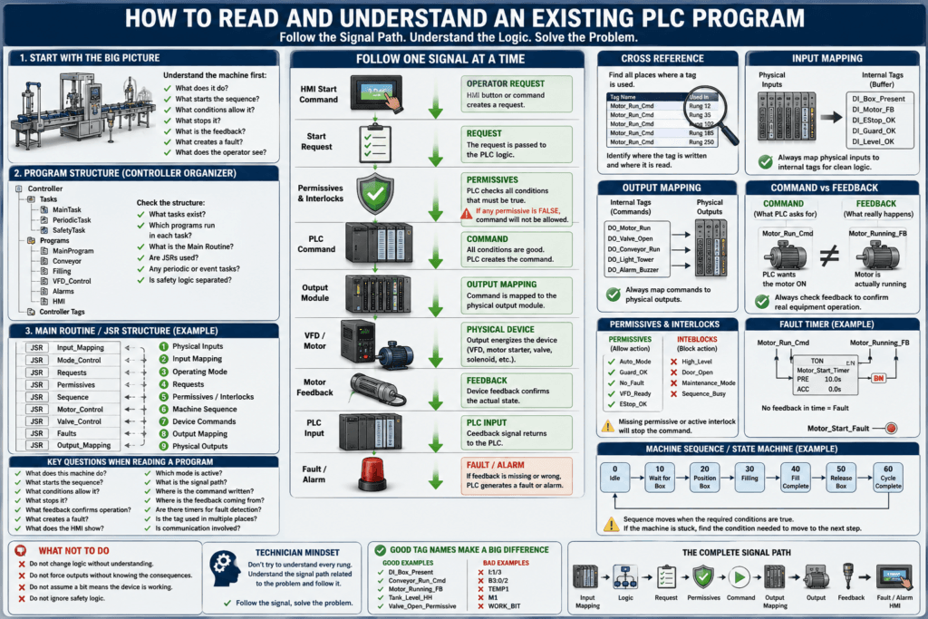
Opening an unfamiliar PLC program can feel overwhelming.
You may see:
- Dozens of routines
- Hundreds or thousands of tags
- Timers and counters everywhere
- Interlocks
- Permissives
- Fault logic
- HMI commands
- VFD control
- Analog signals
- Communication logic
- Old logic that nobody remembers
- Comments that may or may not be accurate
The biggest mistake is trying to understand every rung immediately.
An automation technician should approach an existing PLC program the same way they troubleshoot a machine:
Start with the overall process, then follow the signal path.
The goal is not to memorize the program.
The goal is to understand:
What does the machine do?

What starts the sequence?

What conditions allow it to run?

What stops it?

What feedback confirms operation?

What creates a fault?

What does the operator see?
Once you understand those questions, even a large PLC program becomes much easier to navigate.
1. Understand the Machine Before the PLC Code
Before studying ladder logic, look at the actual equipment.
Identify the major components.
For example:
PLC
Remote I/O
HMI
VFDs
Motors
Solenoid valves
Photoelectric sensors
Limit switches
Pressure switches
Level sensors
Analog transmitters
Safety devices
Then understand the basic process.
Imagine a simple filling machine.
The sequence might be:
Box Arrives
     ↓
Box Sensor Detects Box
     ↓
Conveyor Stops
     ↓
Fill Valve Opens
     ↓
Product Fills Box
     ↓
Target Weight Reached
     ↓
Valve Closes
     ↓
Conveyor Starts
That simple process description gives you something extremely valuable:
a roadmap for reading the PLC program.
2. Start at the Controller Organizer
In Studio 5000, don’t immediately open random routines.
First examine the controller structure.
A typical project may look like:
Controller
│
├── Tasks
│
│   ├── MainTask
│   │
│   ├── PeriodicTask
│   │
│   └── SafetyTask
│
├── Programs
│   ├── MainProgram
│   ├── Conveyor
│   ├── Filling
│   ├── VFD_Control
│   ├── Alarms
│   └── HMI
│
└── Controller Tags
This tells you how the programmer organized the application.
Ask:
What tasks exist?

Which programs execute inside each task?

Which routine is the MainRoutine?

Are JSR instructions being used?

Are there periodic tasks?

Are there event tasks?

Is safety logic separated?
Understanding the execution structure is much more important than immediately understanding individual rungs.
3. Find the Main Routine
The Main Routine usually gives you the best starting point.
You may see something like:
JSR Input_Mapping

JSR Mode_Control

JSR Requests

JSR Permissives

JSR Sequence

JSR Motor_Control

JSR Valve_Control

JSR Faults

JSR Output_Mapping
This is extremely helpful because the program structure almost becomes a table of contents.
You can now study the program one section at a time.
For example:
Physical Inputs
      ↓
Input Mapping
      ↓
Operating Mode
      ↓
Requests
      ↓
Permissives / Interlocks
      ↓
Machine Sequence
      ↓
Device Commands
      ↓
Output Mapping
      ↓
Physical Outputs
This is much easier than randomly opening routines.
4. Find the Input Mapping
One of the first things I like to locate is the input mapping or input buffering logic.
For example:
Local:1:I.Data.0
        |
        +----> DI_Box_Present
or:
XIC Local:1:I.Data.0
OTE DI_Box_Present
Now you know:
Physical Input

Local:1:I.Data.0
        ↓

Internal PLC Tag

DI_Box_Present
That internal tag may then be used throughout the program.
Instead of searching for:
Local:1:I.Data.0you can now follow:
DI_Box_PresentThis is one reason why good PLC programs use input buffering.
5. Follow One Signal at a Time
This is one of the most effective PLC troubleshooting techniques.
Suppose the operator says:
“The conveyor will not start.”
Find the conveyor command.
For example:
DO_Conveyor_RunThen work backward.
You may discover:
DO_Conveyor_Run
        ↑
Conveyor_Run_Cmd
        ↑
Conveyor_Run_Permissive
        ↑
Auto_Mode
Machine_Run
No_Fault
Guard_OK
EStop_OK
Motor_Ready
Now instead of looking through hundreds of rungs, your troubleshooting path becomes:
Why is Conveyor_Run_Cmd OFF?Then:
Which condition is preventing the command?This technique is far more efficient than scrolling randomly through ladder logic.
6. Learn to Use Cross Reference
Cross Reference is one of the most powerful tools available when reading an existing PLC program.
Suppose you find:
Conveyor_Run_CmdCross-reference the tag.
You may find it used in:
Rung 12 — Command Logic
Rung 35 — Output Mapping
Rung 102 — HMI Status
Rung 185 — Fault Detection
Now you can determine:
Where is the tag written?

Where is it read?

What logic controls it?

What outputs depend on it?

What alarms depend on it?
Pay special attention to instructions that write to the tag.
For example:
OTE
OTL
OTU
MOV
COP
CPS
MSG
These instructions may change the tag’s value.
7. Find the Output Mapping
Once you understand the command, find where it reaches the physical output.
Example:
Conveyor_Run_Cmd
        |
        +----> Local:2:O.Data.3
or:
XIC Conveyor_Run_Cmd
OTE Local:2:O.Data.3
This gives you the complete command path:
Operator Request
      ↓
PLC Logic
      ↓
Conveyor_Run_Cmd
      ↓
Output Mapping
      ↓
Local:2:O.Data.3
      ↓
Output Module
      ↓
Motor Starter / VFD
      ↓
Motor
This is the type of signal path an automation technician should learn to follow.
8. Separate Commands From Feedback
One of the most important concepts when reading industrial PLC logic is understanding the difference between:
Commandand:
FeedbackExample:
Conveyor_Run_Cmdmeans:
The PLC is asking the conveyor to run.
But:
Conveyor_Running_FBmeans:
The machine is confirming that the conveyor is actually running.
These are not the same thing.
The PLC may command:
Conveyor_Run_Cmd = 1while:
Conveyor_Running_FB = 0That usually indicates a problem outside the command logic.
Possible causes include:
VFD fault
Motor overload
Contactor failure
Broken wiring
Feedback sensor failure
Communication failure
Motor starter problem
9. Look for Feedback Timers
Industrial PLC programs often use timers to verify equipment response.
Example:
Conveyor_Run_Cmd
AND
NOT Conveyor_Running_FB
        ↓
TON Conveyor_Start_Timer
If the motor does not provide feedback within the allowed time:
Conveyor_Start_Faultmay become active.
Conceptually:
Run Command
     ↓
Wait for Feedback
     ↓
Feedback Received?
   /          \
 YES          NO
  |            |
Run OK      Timer Expires
               |
               ↓
         Motor Start Fault
When troubleshooting, these timers can tell you exactly what the PLC expected to happen.
10. Find the Permissives
A permissive is a condition that must be true before an action is allowed.
Imagine a pump.
The PLC might require:
Auto_Mode
AND
Tank_Level_OK
AND
Valve_Open_FB
AND
No_Overload
AND
VFD_Ready
before allowing:
Pump_Run_PermissiveThe final command could then be:
Pump_Start_Request
AND
Pump_Run_Permissive
        ↓
Pump_Run_Cmd
If the pump does not start, the question becomes:
Which permissive is missing?
This is one of the fastest ways to troubleshoot machine logic.
11. Find the Interlocks
Permissives allow operation.
Interlocks prevent unsafe or undesirable operation.
Example:
High_Levelmay prevent a tank from filling.
Another example:
Valve_A_Openmay prevent:
Valve_B_Openif the two valves must never be open simultaneously.
Conceptually:
Start Request
      +
Permissives
      +
No Interlocks
      ↓
Command
Whenever equipment refuses to operate, look for both:
Missing permissivesand:
Active interlocks12. Identify the Operating Modes
Machines commonly have operating modes such as:
AUTO
MANUAL
HAND
OFF
MAINTENANCE
SETUP
JOG
BYPASS
Before troubleshooting a machine command, determine which mode is active.
For example:
Auto_Mode
Manual_Mode
Maintenance_Mode
The same motor may have completely different command logic depending on the operating mode.
Example:
AUTO MODE

Sequence_Run_Request
        ↓
Motor_Run_Cmd
versus:
MANUAL MODE

HMI_Motor_Start_PB
        ↓
Motor_Run_Cmd
Understanding the mode logic can eliminate a lot of confusion.
13. Identify Requests, Commands, and Outputs
A well-structured PLC program often has multiple layers.
For example:
Motor_Start_Request
        ↓
Motor_Run_Permissive
        ↓
Motor_Run_Cmd
        ↓
DO_Motor_Run
        ↓
Physical Output
Each signal represents something different.
Request
Something wants the motor to run.
Motor_Start_RequestCommand
The PLC has approved the request.
Motor_Run_CmdOutput
The PLC is energizing the physical output.
DO_Motor_RunThis separation makes troubleshooting much easier.
14. Understand the Machine Sequence
Many machines are controlled using sequences or state machines.
You might find tags such as:
Machine_State
Sequence_Step
Current_Step
Step_Number
with values such as:
0   Idle
10  Waiting_For_Box
20  Positioning
30  Filling
40  Fill_Complete
50  Releasing_Box
60  Cycle_Complete
Do not analyze every rung first.
Create your own simple sequence diagram:
Idle
 ↓
Wait for Box
 ↓
Position Box
 ↓
Open Valve
 ↓
Fill
 ↓
Close Valve
 ↓
Release Box
 ↓
Idle
Once you understand the sequence, the ladder logic becomes much easier to follow.
15. Find the Transition Conditions
A sequence only moves when something happens.
For example:
Step 20
AND
Box_In_Position
        ↓
Move to Step 30
Then:
Step 30
AND
Target_Weight_Reached
        ↓
Move to Step 40
When the machine becomes stuck in a sequence, ask:
What condition is required to leave the current step?
This is one of the most useful troubleshooting questions you can ask.
16. Find the Fault Logic
Locate routines with names such as:
Faults
Alarms
Diagnostics
Equipment_Faults
Motor_Faults
Process_Alarms
Typical fault logic may include:
Motor commanded ON
+
No motor feedback
+
Timer expires
        ↓
Motor_Start_Fault
or:
Valve_Open_Cmd
+
No Valve_Open_FB
+
Timer expires
        ↓
Valve_Open_Fault
Understanding fault logic helps explain what the PLC expects from the field equipment.
17. Understand Latched Faults
Many industrial faults remain active even after the original problem disappears.
Example:
Motor_Start_Fault
        ↓
OTL Motor_Fault
Then the fault may require:
Fault_Reset
        ↓
OTU Motor_Fault
This is important during troubleshooting.
The condition causing the fault may already be gone, but the fault bit remains latched waiting for operator acknowledgement or reset.
18. Check HMI Commands Carefully
Do not assume that pressing an HMI button directly energizes an output.
A typical signal path may be:
HMI Start Button
      ↓
HMI_Start_Request
      ↓
Machine_Start_Request
      ↓
Permissive Check
      ↓
Run_Command
      ↓
Physical Output
The HMI usually creates a request.
The PLC decides whether the action is allowed.
That distinction is extremely important.
19. Do Not Trust the HMI Alone
Suppose the HMI displays:
Motor RunningThat indicator could be based on:
Motor_Run_Cmdinstead of:
Motor_Running_FBThose two signals mean very different things.
A good technician should determine exactly which PLC tag drives the HMI indicator.
Whenever possible, verify:
PLC Command
Physical Output
Field Voltage
Equipment Operation
Feedback Signal
The HMI is a diagnostic tool, but it should not be your only source of truth.
20. Understand Aliases and Module Tags
Allen-Bradley programs frequently use alias tags.
Example:
PE_Box_Presentmay be an alias for:
Local:3:I.Data.5This is useful because:
PE_Box_Presentis much easier to understand than a raw I/O address.
Always check whether a tag is:
Base Tag
Alias Tag
Program Tag
Controller Tag
Produced Tag
Consumed Tag
Module-Defined Tag
This can explain where the data is really coming from.
21. Watch for Produced and Consumed Tags
In larger systems, the tag you are troubleshooting may not originate in the PLC you are currently online with.
For example:
Line2_Readycould be a consumed tag coming from another ControlLogix or CompactLogix controller.
Signal path:
PLC #2
Line_Ready
      ↓
Produced Tag
      ↓
EtherNet/IP
      ↓
Consumed Tag
      ↓
PLC #1
If the value is wrong, the problem may be:
PLC #2 logic
Network communication
Produced/Consumed connection
Module configuration
Controller fault
not PLC #1 logic.
22. Watch for MSG Instructions
Older systems or mixed PLC architectures may use MSG instructions.
A MSG instruction may transfer data between:
ControlLogix
CompactLogix
SLC 500
PLC-5
Other Ethernet devices
When analyzing a MSG, determine:
What data is being transferred?

Who is the source?

Who is the destination?

What is the communication path?

Is the MSG completing successfully?

Is an error code present?
Communication logic can sometimes make a local machine problem appear to be a logic problem.
23. Identify Analog Scaling
Analog signals can be confusing when reading an unfamiliar program.
You may find raw values such as:
0
3277
16383
32767
or engineering values such as:
0–100 PSI
0–200 °F
0–19000 kg
0–100 %
Look for scaling instructions or calculations.
For example:
Raw_Input
      ↓
Scaling Logic
      ↓
Tank_Level_PV
or:
4–20 mA
      ↓
Analog Input Module
      ↓
Raw Count
      ↓
Scale
      ↓
Engineering Units
When troubleshooting analog values, always know whether you are looking at:
Raw counts
mA
Volts
Engineering units
Scaled percentage
24. Search for Duplicate Output Instructions
One dangerous programming practice is writing the same tag from multiple locations.
For example:
Rung 20
OTE Motor_Run
and:
Rung 250
OTE Motor_Run
The final state may depend on PLC scan order.
This can create confusing behavior.
Use Cross Reference to identify every location that writes to critical tags.
Be especially cautious with:
Outputs
Commands
Sequence states
Fault bits
Mode bits
25. Be Careful With OTL and OTU Instructions
Latched bits require special attention.
Example:
OTL Pump_Run_Requestmay be located in one routine while:
OTU Pump_Run_Requestis located somewhere completely different.
Cross-reference both instructions.
Ask:
What sets the bit?

What resets the bit?

Can multiple conditions set it?

What happens after a power cycle?
Never assume a latched bit behaves like a standard OTE.
26. Read Tags Before Rungs
Sometimes you can learn a surprising amount just by looking at tag names.
For example:
DI_PE_BoxPresent
DI_Motor_FB
DI_Motor_OL
DO_Conveyor_Run
Conveyor_Run_Cmd
Conveyor_Run_Permissive
Conveyor_Start_Fault
HMI_Conveyor_Start
Even without seeing the ladder logic, you can already guess the signal structure:
HMI Request
      ↓
Run Permissive
      ↓
Run Command
      ↓
Output
      ↓
Motor
      ↓
Feedback
      ↓
Fault Monitoring
Good tag naming makes programs dramatically easier to understand.
27. Create Your Own Signal Map
When working with a complicated machine, write down the signal path.
Example:
HMI Start
   ↓
HMI_Start_PB
   ↓
Start_Request
   ↓
Run_Permissive
   ↓
Motor_Run_Cmd
   ↓
DO_Motor_Run
   ↓
Local:4:O.Data.2
   ↓
VFD
   ↓
Motor
   ↓
Motor_Running_FB
   ↓
Local:3:I.Data.7
This becomes your troubleshooting roadmap.
You do not need to understand the entire PLC program.
You need to understand the part of the program related to the problem.
28. Example — Conveyor Will Not Start
Suppose production calls automation because:
Conveyor 1 will not start.
Do not immediately change the PLC program.
Start with the signal path.
Step 1 — Operator Request
Check:
HMI_Conveyor_StartIs it changing?
If not, investigate:
HMI
Communication
HMI tag configuration
Operator mode
Step 2 — Start Request
Check:
Conveyor_Start_RequestIf the HMI command is present but the request is not generated, investigate the request logic.
Step 3 — Permissives
Check:
Conveyor_Run_PermissiveThen inspect its conditions.
For example:
Machine_Enable
EStop_OK
Guard_OK
No_Conveyor_Fault
VFD_Ready
Auto_Mode
Find the missing permissive.
Step 4 — Command
Check:
Conveyor_Run_CmdIf the permissive is valid but the command is missing, inspect the command logic.
Step 5 — Physical Output
Check:
DO_Conveyor_Runand then the real output module.
Local:4:O.Data.2If the PLC output is ON, move outside the PLC.
Step 6 — Field Device
Check:
Output module
Terminal block
24 VDC / 120 VAC control voltage
Contactor
VFD
Motor starter
Motor
At this point, changing ladder logic would probably be the wrong troubleshooting action.
Step 7 — Feedback
Finally verify:
Conveyor_Running_FBThe complete path is:
HMI
 ↓
Request
 ↓
Permissive
 ↓
Command
 ↓
PLC Output
 ↓
Field Device
 ↓
Motor
 ↓
Feedback
 ↓
PLC Input
This is the technician mindset.
29. A Practical Routine for Reading Any PLC Program
When opening an unfamiliar project, I recommend this order:
1. Understand the physical machine

2. Review the Controller Organizer

3. Identify Tasks and Programs

4. Find the Main Routine

5. Identify JSRs or program execution order

6. Locate input mapping

7. Locate output mapping

8. Identify operating modes

9. Find permissives

10. Find interlocks

11. Find command logic

12. Find equipment feedback

13. Find fault and alarm routines

14. Identify machine sequence/state logic

15. Review HMI interface tags

16. Identify communications

17. Cross-reference important signals

18. Draw the signal path
Do not try to understand everything simultaneously.
30. What Not to Do
When analyzing an existing PLC program, avoid these common mistakes.
Do Not Immediately Modify Logic
If the machine worked before, the PLC program is often not the first thing that failed.
Check the field equipment first.
Do Not Force Outputs Without Understanding the Consequences
Forcing an output can bypass normal machine logic.
That can create:
Unexpected motion
Product spills
Mechanical damage
Unsafe conditions
Sequence problems
Understand the circuit before forcing anything.
Do Not Assume a PLC Bit Means the Physical Device Is Working
Remember:
Command ≠ FeedbackAlways verify physical operation.
Do Not Ignore Safety Logic
Standard PLC logic and machine safety are different systems.
Never bypass or modify:
Emergency stops
Guard switches
Light curtains
Safety relays
Safety PLC logic
without following the site’s approved safety procedure.
Technician Mindset
When reading an unfamiliar PLC program, don’t ask:
How do I understand these 2,000 rungs?
Ask:
What signal am I trying to understand?
Then follow it.
A technician troubleshooting a valve might follow:
HMI_Open_Request
        ↓
Valve_Open_Request
        ↓
Valve_Open_Permissive
        ↓
Valve_Open_Cmd
        ↓
DO_Valve_Open
        ↓
Solenoid
        ↓
Valve
        ↓
Valve_Open_FB
        ↓
Fault Logic
A technician troubleshooting a motor might follow:
Start Request
        ↓
Run Permissive
        ↓
Run Command
        ↓
PLC Output
        ↓
VFD / Starter
        ↓
Motor
        ↓
Running Feedback
        ↓
Fault Timer
This method works on small machines and very large industrial systems.
Key Terms
Cross Reference
A PLC programming tool used to locate every place where a tag is read or written.
Input Mapping
Logic that transfers physical input data into meaningful internal PLC tags.
Output Mapping
Logic that transfers PLC commands to physical output module points.
Command
A PLC instruction requesting a device to operate.
Feedback
A signal confirming that the physical device actually reached the requested state.
Permissive
A condition that must be true before an action is allowed.
Interlock
A condition that prevents an action because another machine or process condition makes it undesirable or unsafe.
Request
A signal indicating that some part of the program or operator wants an action to occur.
Sequence / State Machine
Logic that controls the machine through defined operating steps.
Fault Timer
A timer that monitors whether equipment responds within the expected amount of time.
Final Thoughts
Large PLC programs become much easier when you stop looking at them as thousands of individual instructions.
Instead, look for the signal flow.
A well-designed industrial control system often follows a structure similar to:
Physical Input
      ↓
Input Mapping
      ↓
PLC Logic
      ↓
Request
      ↓
Permissives / Interlocks
      ↓
Command
      ↓
Output Mapping
      ↓
Physical Output
      ↓
Machine
      ↓
Feedback
      ↓
Fault / Alarm
      ↓
HMI
When troubleshooting, start with the symptom and follow that chain.
You usually do not need to understand the entire PLC program to solve a problem.
You need to understand the relevant signal path.
That is one of the most important skills an automation technician can develop.