29. PLC Communication Basics: HMI, VFD, Remote I/O, and SCADA ( 29 of 35 )
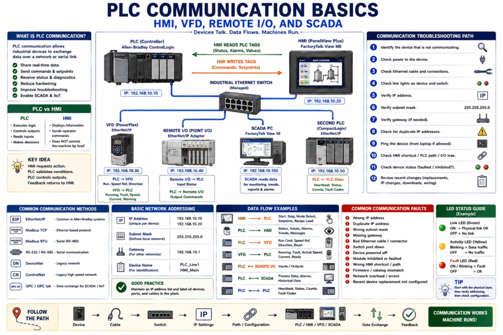
PLC Communication Basics
Modern PLC systems rarely work alone.
A PLC may communicate with:
HMI panels
VFDs
Remote I/O
Servo drives
Robots
Barcode readers
Vision systems
SCADA computers
Industrial switches
Other PLCs
Data collection systems
In older systems, many signals were hardwired point-to-point.
Example:
PLC output → VFD start input
VFD running contact → PLC input
VFD fault contact → PLC input
That still exists today, but modern systems often use industrial networks to exchange more information with fewer wires.
A PLC communication port allows the PLC to communicate with devices such as laptops, HMIs, SCADA PCs, and drives. The source material also notes that different PLCs may have ports such as RS-232, RS-422, RS-485, Ethernet, or other communication interfaces depending on the model.
Why PLC Communication Matters
PLC communication allows devices to exchange data.
Example:
HMI reads PLC tags
VFD receives speed command from PLC
Remote I/O sends input status to PLC
SCADA collects production data
PLC sends status to another PLC
Laptop goes online with controller
Without communication, the PLC may still be powered and running, but the full control system may not operate correctly.
Common symptoms include:
HMI communication fault
VFD communication fault
Remote I/O fault
SCADA values not updating
PLC-to-PLC message failure
Engineering laptop cannot go online
Device unavailable in I/O tree
Network status LED flashing red
Many communication problems are not caused by bad logic. They are caused by power, cable, switch, IP address, subnet, device path, or configuration issues.
PLC Communication vs Hardwired I/O
Before understanding network communication, it helps to compare it with hardwired I/O.
Hardwired Control
Hardwired control uses physical wires for each signal.
Example:
PLC DO → VFD Start Input
VFD Running Relay → PLC DI
VFD Fault Relay → PLC DI
Analog Output → VFD Speed Reference
Advantages:
Simple to understand
Easy to test with a meter
Works without network configuration
Good for basic signals
Limitations:
More wiring
More I/O points required
Limited diagnostics
Less data available to HMI or SCADA
Harder to get detailed device status
Networked Control
Networked control uses communication data instead of separate wires for every signal.
Example:
PLC ↔ Ethernet Switch ↔ VFD
PLC ↔ Ethernet Switch ↔ HMI
PLC ↔ Ethernet Switch ↔ Remote I/O
The PLC may send:
Run command
Speed reference
Direction
Fault reset
Enable command
The device may send back:
Running status
Ready status
Fault status
Fault code
Actual speed
Motor current
Warning status
Communication health
Advantages:
More diagnostics
Less hardwiring
Better HMI information
More data for troubleshooting
Easier integration with SCADA
Limitations:
Requires IP configuration
Requires PLC setup
Communication fault can stop machine
Technician needs basic networking skills
Common PLC Communication Devices
1. HMI Communication
The HMI reads and writes PLC tags.
Example:
HMI reads:
Motor_Running_FB
Tank_Level_Percent
Machine_Faulted
Current_Step

HMI writes:
HMI_Start_PB
HMI_Stop_PB
HMI_Reset_PB
HMI_Speed_Setpoint
The HMI is the operator window into the PLC.
The PLC source material explains that HMI systems give operators selective read/write access to PLC memory locations, allowing them to monitor values, view alarms, and adjust parameters through a dedicated operator screen.
2. VFD Communication
A VFD may be controlled through hardwired signals or through a network.
With network communication, the PLC can send commands and receive detailed feedback.
PLC sends to VFD:
Run command
Stop command
Speed reference
Direction
Fault reset
Acceleration time
Deceleration time
VFD sends to PLC:
Drive ready
Drive running
Drive faulted
Actual frequency
Output current
Fault code
Warning code
At speed status
This gives the technician more information than simple hardwired Start/Fault contacts.
3. Remote I/O Communication
Remote I/O allows input and output modules to be installed away from the main PLC rack.
Example:
Main PLC panel
    ↓
Industrial Ethernet switch
    ↓
Remote I/O block near machine
Remote I/O is useful because it reduces long field wiring back to the main panel.
Instead of running every sensor wire to the PLC cabinet, the field devices connect to remote I/O located near the machine.
The remote I/O then sends data to the PLC over the network.
4. SCADA Communication
SCADA systems collect and display data from PLCs.
SCADA may show:
Production status
Process values
Alarms
Trends
Historical data
Batch reports
Downtime data
Energy data
SCADA usually reads PLC data through an industrial communication driver, OPC server, or network protocol.
A PLC can control the machine locally, while SCADA monitors the process at a higher level.
5. PLC-to-PLC Communication
Sometimes one PLC needs to exchange data with another PLC.
Examples:
Line status
Machine ready
Production count
Fault code
Start permissive
Heartbeat signal
Robot cell ready
Upstream/downstream conveyor status
PLC-to-PLC communication may use:
Produced / Consumed Tags
MSG instructions
Modbus TCP
EtherNet/IP messaging
Serial communication
Other protocol-specific methods
This is common when multiple machines must coordinate production.
Common Industrial Communication Methods
PLC systems may use different communication methods depending on the age and design of the system.
Common methods include:
EtherNet/IP
Modbus TCP
Modbus RTU
RS-232
RS-485
DeviceNet
ControlNet
PROFINET
Remote I/O networks
OPC / OPC UA
Serial ASCII
For a technician, the most important thing is not memorizing every protocol at once.
The important thing is to understand:
What device is talking?
What protocol is used?
What cable is used?
What address or path is configured?
What data should be exchanged?
What status indicates healthy communication?
EtherNet/IP in Allen-Bradley Systems
In many Allen-Bradley systems, EtherNet/IP is used to connect:
CompactLogix
ControlLogix
PanelView Plus
PowerFlex drives
POINT I/O
FLEX I/O
ArmorBlock I/O
Stratix switches
SCADA computers
A typical architecture may look like:
PLC
    ↓
Industrial Ethernet Switch
    ↓          ↓          ↓
HMI        VFD       Remote I/O
Each device usually needs:
IP address
Subnet mask
Gateway if needed
Device name
Correct PLC path
Correct I/O tree configuration
Basic Network Settings
For Ethernet-based PLC communication, the common settings are:
IP Address
Subnet Mask
Gateway
Device Name
Communication Path
A previous source from your automation roadmap notes that a small mistake in these settings can cause HMI communication loss, VFD communication faults, remote I/O faults, SCADA tags not updating, or PLC-to-PLC message failures.
IP Address
The IP address identifies a device on the network.
Example:
PLC:        192.168.10.10
HMI:        192.168.10.20
VFD:        192.168.10.30
Remote I/O: 192.168.10.40
SCADA:      192.168.10.100
Each device should have a unique IP address.
Two devices with the same IP address can create intermittent communication problems.
Subnet Mask
The subnet mask defines which devices are considered local to the same network.
Common subnet mask:
255.255.255.0Example:
PLC: 192.168.10.10
HMI: 192.168.10.20
With subnet mask 255.255.255.0, these devices are usually on the same network.
But:
PLC: 192.168.10.10
HMI: 192.168.20.20
These are not on the same subnet if the subnet mask is 255.255.255.0.
Gateway
A gateway is used when communication must go outside the local subnet.
Example:
PLC network:   192.168.10.x
SCADA network: 192.168.20.x
If SCADA is on another subnet, the PLC or network may need a correct gateway or routing configuration.
Without the correct gateway, local HMI communication may work, but SCADA communication may fail.
Link Lights
Ethernet ports usually have status LEDs.
Common meaning:
Link light ON = physical connection detected
Activity blinking = traffic moving
No link light = no physical connection
If there is no link light, check:
Cable
Connector
Switch port
Device power
Wrong Ethernet port
Bad patch cable
Bad RJ45 connector
Damaged port
Fiber converter if used
Do not start by changing PLC logic if there is no physical link.
Start with the cable and port.
Ping Test
A ping test checks if one device can reach another over the network.
Example from a laptop:
ping 192.168.10.10If the PLC replies, basic network reachability is working.
But important:
A successful ping does not prove the HMI shortcut is correct.
A successful ping does not prove EtherNet/IP I/O connection is healthy.
A successful ping does not prove the PLC tag path is correct.
Ping is a useful test, but it is only one layer of troubleshooting.
Communication Path
In many PLC systems, communication depends not only on IP address, but also on the correct path.
Examples:
HMI shortcut path to PLC
FactoryTalk Linx path
RSLinx / FactoryTalk Linx driver
PLC I/O tree path
MSG instruction path
SCADA tag path
Produced/Consumed tag connection
A device can have the correct IP address and still fail if the path is wrong.
Example:
PLC was replaced.
New PLC has same IP address.
HMI still points to old controller path or shortcut.
Result: HMI communication fault.
I/O Tree Communication
In Studio 5000 / Logix systems, networked devices are commonly configured in the I/O tree.
Examples:
Ethernet module
Remote I/O adapter
PowerFlex drive
Servo drive
Communication adapter
If a device in the I/O tree loses communication, the PLC may show module fault status.
Common causes:
Device powered off
Wrong IP address
Cable disconnected
Switch port issue
Wrong module profile
Electronic keying mismatch
Firmware mismatch
Device inhibited
Wrong slot/module configuration
Network overload
The PLC may still be running, but the machine can stop because a required I/O connection is faulted.
Device Inhibit
In Studio 5000, a module may be inhibited.
When inhibited, the PLC does not actively communicate with that module.
This can be useful for testing, but it can also cause confusion.
Possible symptom:
Device is powered and connected,
but PLC is not communicating with it.
Check:
Is the module inhibited?
Was it inhibited during troubleshooting?
Was it re-enabled after testing?
Is the module fault still active?
This is very important in real plant troubleshooting.
Produced / Consumed Tags
Produced and consumed tags are used for PLC-to-PLC communication in Logix systems.
Simple concept:
Producer PLC = publishes data
Consumer PLC = receives data
Example:
Line1_PLC produces:
Line1_Running
Line1_Faulted
Line1_Ready
Line1_Production_Count

Line2_PLC consumes:
Line1_Status_Data
Produced/Consumed tags are good for fast, scheduled PLC-to-PLC data exchange.
Common uses:
Machine ready status
Heartbeat
Fault status
Production count
Interlock between machines
Line coordination
MSG Instructions
MSG instructions are another way to exchange data.
Simple concept:
MSG instruction = PLC sends a request to read or write dataMSG instructions can be useful when:
Data is needed occasionally
Communication is event-based
Reading data from another PLC
Writing a command to another controller
Getting data from a legacy PLC
Produced/Consumed tags are usually better for continuous cyclic data.
MSG instructions are often better for occasional data exchange.
Heartbeat Signal
A heartbeat is a signal used to prove communication is alive.
Example:
PLC A toggles Heartbeat bit every second.
PLC B watches that bit.
If it stops changing, PLC B knows communication may be lost.
Heartbeat signals are useful for:
PLC-to-PLC communication
Robot communication
SCADA watchdogs
Remote device status
Machine coordination
A heartbeat should not only be ON all the time.
It should change state or update so the receiving device knows the data is fresh.
Communication Faults
A communication fault happens when expected data exchange is lost or invalid.
Common communication faults include:
HMI cannot read PLC
VFD not communicating
Remote I/O adapter faulted
Ethernet module fault
PLC-to-PLC heartbeat lost
SCADA tags stale
Device connection timeout
Duplicate IP detected
I/O connection lost
A communication fault may be caused by network hardware, device configuration, software path, or power.
Common Communication Problems
1. Wrong IP Address
Example:
VFD was replaced.
New VFD has default IP.
PLC I/O tree still expects old IP.
Result:
PLC shows VFD communication fault.2. Duplicate IP Address
Example:
PLC: 192.168.10.10
VFD: 192.168.10.10
Possible symptoms:
Intermittent communication
HMI freezes
Device connects and disconnects
Ping replies inconsistent
One device works only when the other is off
3. Bad Cable or Connector
Symptoms:
No link light
Link drops randomly
Communication works when cable is moved
Switch port errors increase
Device disconnects during vibration
Check:
RJ45 connector
Cable jacket
Patch panel
Switch port
Cable route
Strain relief
4. Wrong Subnet
Example:
PLC: 192.168.10.10
HMI: 192.168.20.20
Subnet: 255.255.255.0
These devices may not communicate directly because they are on different networks.
5. Wrong HMI Shortcut
The HMI may be pointing to the wrong controller path.
Possible after:
PLC replacement
HMI runtime update
Backup restore
IP address change
Controller name change
FactoryTalk Linx shortcut change
6. Device Powered Off
Never forget the basics.
A communication fault may simply mean:
Device has no power.
Remote rack power supply failed.
VFD control power is off.
Switch lost 24 VDC.
HMI is rebooting.
7. Module Inhibited
A device may be inhibited in the PLC project.
Possible symptom:
Device physically healthy,
but PLC does not actively connect to it.
8. Electronic Keying / Module Mismatch
In Logix systems, the PLC may expect a specific module type or revision.
If the physical device does not match the configuration, the connection may fault.
Possible after:
Replacing module
Replacing VFD
Replacing remote I/O adapter
Changing firmware
Installing different catalog number
Basic Communication Troubleshooting Path
Use this method:
1. Identify which device is not communicating.
2. Check device power.
3. Check PLC power and Run status.
4. Check Ethernet link lights.
5. Check cable and switch port.
6. Verify IP address.
7. Verify subnet mask.
8. Verify gateway if needed.
9. Check for duplicate IP.
10. Ping the device if allowed.
11. Check PLC I/O tree or HMI shortcut.
12. Check module inhibit or fault status.
13. Check recent changes.
14. Document root cause.
This method prevents guessing.
Example 1 — HMI Cannot Communicate with PLC
Symptom
HMI displays:
PLC Communication Error
Check
Is PLC powered?
Is HMI powered?
Is switch powered?
Are link lights ON?
Is PLC IP correct?
Is HMI IP correct?
Is HMI shortcut correct?
Are PLC and HMI on same subnet?
Can laptop ping PLC?
Was PLC replaced recently?
Was HMI runtime changed?
Possible Root Causes
Bad Ethernet cable
Wrong PLC IP
Wrong HMI shortcut
Duplicate IP
Switch port issue
PLC powered off
HMI runtime points to old controller
Example 2 — VFD Communication Fault
Symptom
PLC shows VFD communication fault.Check
Is VFD powered?
Is VFD Ethernet adapter powered?
Is cable connected?
Is link light ON?
Is VFD IP correct?
Does PLC I/O tree expect that IP?
Is device inhibited?
Is electronic keying compatible?
Is VFD faulted locally?
Was VFD replaced?
Possible Root Cause
Replacement VFD installed with default IP address.Example 3 — Remote I/O Drops Communication
Symptom
Remote I/O faults randomly.Check
Remote adapter power
24 VDC supply
Ethernet cable
Switch port errors
RJ45 connector
Vibration at connector
IP address
Duplicate IP
Network traffic
Grounding/noise
Device status LEDs
Possible Root Causes
Loose Ethernet connector
Damaged cable
Switch port issue
Remote I/O power dip
Electrical noise
Duplicate IP
Example 4 — Laptop Cannot Go Online with PLC
Symptom
Engineering laptop cannot connect to PLC.Check
Laptop Ethernet adapter selected
Laptop IP address
Laptop subnet mask
PLC IP address
Cable connection
Switch port
Ping test
FactoryTalk Linx / RSLinx path
Firewall
VPN settings
Correct controller selected
Possible problem:
Laptop is on 192.168.20.x,
but PLC is on 192.168.10.x with subnet 255.255.255.0.
Technician Notes: What to Check First
When communication fails, do not start with advanced settings.
Start simple:
Power
Cable
Link light
IP address
Subnet
Path
Recent changes
A strong technician asks:
What device is not talking?
Who is it supposed to talk to?
What network path connects them?
Is the physical link healthy?
Are the addresses correct?
Did anything change recently?
Best Practices for PLC Communication
Use these habits:
Keep an updated IP address list.
Label Ethernet cables.
Label switch ports.
Document device names.
Record panel and machine location.
Save PLC and HMI backups.
Record VFD IP settings before replacement.
Avoid duplicate IPs.
Use static IPs or controlled reservations for critical devices.
Check link lights before software troubleshooting.
Document switch ports.
Backup managed switch configurations.
Do not connect unknown devices to OT networks without approval.
Good documentation reduces downtime.
Communication Checklist for the Field
Device powered ON
Correct Ethernet cable connected
Link lights ON
Switch port active
Correct IP address
Correct subnet mask
Correct gateway if needed
No duplicate IP
Correct PLC I/O tree entry
Correct HMI shortcut
Correct SCADA path
Correct module profile
Module not inhibited
No firmware/keying issue
No recent wiring change
No recent replacement left unconfigured
Documentation updated
Automation Technician Notes
For an Automation Technician, PLC communication troubleshooting is about following the communication path.
Device → Cable → Switch → IP Settings → Communication Path → PLC / HMI / VFD / SCADAA communication problem can look complicated, but many root causes are simple:
Wrong IP
Wrong subnet
Bad cable
No power
Duplicate IP
Wrong shortcut
Device inhibited
Old configuration after replacement
The goal is to prove each layer.
Do not guess.
Key Terms
| Term | Meaning |
|---|---|
| PLC Communication | Data exchange between PLC and other devices |
| Ethernet/IP | Common industrial Ethernet protocol in Allen-Bradley systems |
| IP Address | Network address of a device |
| Subnet Mask | Defines local network range |
| Gateway | Path to other networks |
| HMI Shortcut | Communication path from HMI to PLC |
| I/O Tree | PLC configuration area for networked modules |
| Remote I/O | I/O modules connected over a network |
| Produced Tag | PLC tag published for another PLC |
| Consumed Tag | PLC tag received from another PLC |
| MSG Instruction | PLC instruction used to read/write data |
| Heartbeat | Changing signal used to prove communication is alive |
| Link Light | Ethernet LED showing physical connection |
| Duplicate IP | Two devices using the same IP address |
| Device Inhibit | PLC setting that disables communication to a module |
Final Thoughts
PLC communication is one of the most important skills for modern automation technicians.
A PLC may communicate with HMIs, VFDs, remote I/O, SCADA systems, robots, vision systems, and other PLCs.
When communication fails, the problem may not be the PLC program.
It may be:
Power
Cable
Switch
IP address
Subnet
Gateway
HMI shortcut
I/O tree setup
Module inhibit
Duplicate IP
Device replacement configuration
The professional mindset is simple:
Follow the communication path.
Check the physical link first.
Verify addressing.
Confirm the PLC/HMI path.
Document the root cause.
If the devices cannot find each other, they cannot exchange data.
That simple idea explains many industrial network problems.