19. PLC Scan Cycle: Why Order Matters (19 of 41)
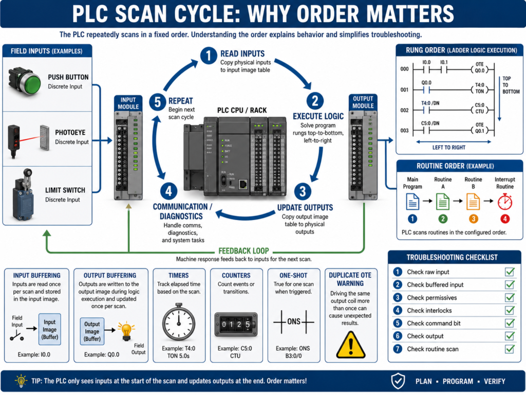
A PLC does not execute logic randomly.
It follows a repeated process called the scan cycle.
Understanding the scan cycle is one of the most important steps in learning PLC troubleshooting and ladder logic.
Many problems that look confusing at first are easier to understand once you know how the PLC reads inputs, solves logic, updates outputs, and repeats the process.
A simple PLC scan cycle looks like this:
1. Read Inputs
2. Execute Logic
3. Update Outputs
4. Perform Communication / Diagnostics
5. Repeat
This cycle happens very fast, usually many times per second.
But even though it happens fast, the order still matters.
1. What Is the PLC Scan Cycle?
The scan cycle is the repeated process the PLC uses to control the machine.
The PLC continuously:
Reads the status of inputs
Solves the program logic
Updates output commands
Communicates with other devices
Repeats the process
The basic idea:
Inputs → Logic → Outputs → RepeatExample:
Photoeye detects a box
        ↓
PLC reads the input
        ↓
Logic decides what to do
        ↓
PLC turns ON an output
        ↓
Machine reacts
        ↓
PLC repeats the scan
The scan cycle is the heartbeat of the PLC.
2. Step 1 — Read Inputs
At the beginning of the scan, the PLC reads the status of its input modules.
Examples:
Start_PB = ON
Stop_PB_OK = ON
Photoeye_BoxPresent = OFF
Overload_OK = ON
LimitSwitch_Home = ON
The PLC stores these input states in memory.
During logic execution, the PLC usually works with the input image or input data it read at that time.
That means the PLC logic is based on the latest input status available during that scan.
3. Step 2 — Execute Logic
After reading inputs, the PLC executes the program.
In ladder logic, this usually means solving rungs from:
Top to bottom
Left to right
Routine by routine
Example:
Rung 1 is solved.
Then Rung 2 is solved.
Then Rung 3 is solved.
Then the next routine is solved.
This order is very important.
If one rung turns ON a bit, a rung below it can use that updated bit during the same scan.
But a rung above it already executed and will not see that new state until the next scan.
4. Step 3 — Update Outputs
After the logic is solved, the PLC updates the physical output modules.
Example:
Motor_Output = ON
Solenoid_Output = OFF
StackLight_Green = ON
AlarmHorn = OFF
The output module then energizes or de-energizes real devices.
Examples:
Relay coil
Solenoid valve
Contactor coil
VFD start input
Stack light
Buzzer
Important:
The PLC output bit in logic may change before the physical output module updates.
This usually happens very fast, but it matters when understanding scan behavior.
5. Step 4 — Communication and Diagnostics
The PLC also handles communication and diagnostics.
This may include:
HMI communication
SCADA communication
VFD communication
Remote I/O updates
Network status
Fault detection
Module diagnostics
Produced and consumed tags
In modern PLC systems, communication can happen asynchronously depending on the controller and network.
But for a technician, the key idea is:
PLC control is a repeated cycle of reading, solving, updating, and communicating.6. Why Order Matters in Ladder Logic
Rung order matters because the PLC solves logic sequentially.
Example:
Rung 1: Motor_Run_Command turns ON
Rung 2: Motor_Output uses Motor_Run_Command
This works as expected because the command is created before the output uses it.
But if the order is reversed:
Rung 1: Motor_Output uses Motor_Run_Command
Rung 2: Motor_Run_Command turns ON
The output may not turn ON until the next scan because the output rung was solved before the command was updated.
Usually this delay is tiny, but in some logic it can cause confusing behavior.
7. Internal Bits Update Immediately in Logic
Internal bits are updated as the logic solves.
Example:
Rung 1: Start_Request turns ON
Rung 2: Run_Command uses Start_Request
If Rung 1 turns ON Start_Request, Rung 2 can use it in the same scan.
This is why logic organization matters.
A clean structure usually follows this order:
Inputs
Requests
Permissives
Interlocks
Commands
Outputs
Feedback
Faults
HMI Status
This makes the program flow easier to understand.
8. Physical Inputs Are Not the Same as Internal Bits
A physical input comes from a real device.
Examples:
Start push button
Photoeye
Limit switch
Pressure switch
Overload contact
An internal bit is created inside the PLC logic.
Examples:
Start_Request
Motor_Run_Command
Auto_Mode
Fault_Active
Permissive_OK
Interlock_Clear
Physical inputs depend on the input module scan.
Internal bits update as the logic executes.
This difference is very important when troubleshooting.
9. Physical Outputs vs Output Commands
A PLC program may use internal output command bits before energizing real outputs.
Example:
Motor_Run_Command
        ↓
Motor_Output
        ↓
Physical PLC output
        ↓
Relay or VFD input
A good program often separates command logic from physical output logic.
Example:
Command Logic:
Start request + permissives + no faults = Motor_Run_Command

Output Logic:
Motor_Run_Command = DO_Motor_Start
This makes troubleshooting easier.
10. Input Buffering
Input buffering means copying raw physical inputs into internal tags.
Example:
Raw Input: Local:1:I.Data.0
Buffered Tag: DI_Start_PB
Why use input buffering?
Cleaner tag names
Easier troubleshooting
One place to invert logic if needed
Consistent program structure
Easier HMI diagnostics
Easier simulation
Example:
DI_Start_PB = Raw_Start_Input
DI_Stop_OK = Raw_Stop_Input
DI_PE_BoxPresent = Raw_Photoeye_Input
Then the program uses the buffered tags instead of raw addresses.
11. Output Buffering
Output buffering means using internal command bits first, then mapping them to physical outputs at the end of the program.
Example:
Internal Command: DO_Motor_Start_Cmd
Physical Output: Local:2:O.Data.0
Why use output buffering?
Keeps output mapping organized
Allows simulation
Centralizes physical output assignments
Makes troubleshooting easier
Prevents scattered output coils everywhere
Improves program readability
A professional structure often places physical outputs near the end of the program.
12. Why Multiple OTEs Can Be a Problem
In ladder logic, using the same output coil in multiple places can cause problems.
Example:
Rung 1: Motor_Output = ON
Rung 10: Motor_Output = OFF
The last rung scanned may determine the final state.
This can confuse new technicians.
This is sometimes called:
Last rung winsBetter practice:
Use one final output rung.
Build the command logic before that rung.
Example:
Motor_Run_Command = Start request + permissives + no interlocks
Motor_Output = Motor_Run_Command
This makes the output easier to troubleshoot.
13. Seal-In Logic and Scan Cycle
Seal-in logic depends on scan behavior.
Example:
Start PB OR Motor_Run_Command
AND Stop OK
AND No Fault
= Motor_Run_Command
When the Start button is pressed, the command turns ON.
Then the command holds itself ON through the seal-in branch after the Start button is released.
Basic idea:
Momentary Start → Run Command latches through logicUnderstanding scan cycle helps explain why seal-in circuits work.
14. One-Shots and the Scan Cycle
A one-shot creates a pulse for one scan.
In Allen-Bradley logic, this is often done with:
ONS
OSR
OSF
A one-shot is useful when you want something to happen once when a condition changes.
Examples:
Increment counter one time
Trigger a message once
Capture a value once
Start a sequence step once
Toggle a bit once
Without a one-shot, a counter might count every scan while a button is held ON.
Example:
Button held for 1 second
PLC scans many times
Counter increments many times
With a one-shot:
Button transitions from OFF to ON
Counter increments once
15. Timers and the Scan Cycle
Timers also depend on scan execution.
A TON timer accumulates time while its rung is true.
Example:
Input condition true
        ↓
Timer starts accumulating
        ↓
Preset reached
        ↓
Timer Done bit turns ON
If the rung goes false, a normal TON resets.
This matters in troubleshooting.
If a timer keeps resetting, the rung condition may be flickering.
Possible causes:
Noisy sensor
Bad input
Loose wire
Interlock flickering
Logic condition unstable
Wrong XIC/XIO
16. Counters and the Scan Cycle
Counters count transitions.
But if programmed incorrectly, they may count too many times.
Example problem:
Photoeye stays ON while box is present.
Counter counts every scan instead of once per box.
Solution:
Use one-shot logic.
Count only the transition.
Example:
Photoeye goes from OFF to ON
        ↓
One-shot pulse
        ↓
Counter increments once
17. Routines and Scan Order
PLC programs are often divided into routines or subroutines.
Examples:
Input_Buffering
Mode_Selection
Requests
Permissives
Interlocks
Commands
Fault_Logic
Alarm_Logic
Output_Buffering
HMI_Status
The order in which routines are called matters.
Example preferred order:
1. Input Buffering
2. Mode Selection
3. Requests
4. Permissives
5. Interlocks
6. Commands
7. Fault Logic
8. Alarm Logic
9. Output Buffering
10. HMI Status
This order creates a logical flow.
Inputs are processed first.
Commands are generated after conditions are known.
Outputs are updated after commands are finalized.
HMI status is updated after logic is complete.
18. What Happens If a Routine Is Not Scanned?
If a routine is not called, its logic does not execute.
This is a common troubleshooting issue.
In RSLogix 500, subroutines must usually be called with a JSR instruction.
Example:
JSR SBR_3If the JSR is missing, the subroutine logic will not run.
Symptoms:
Inputs mapped in that routine do not update.
Outputs in that routine do not change.
Timers do not run.
Fault logic does not work.
HMI status bits stay wrong.
In Studio 5000, make sure the routine is in the correct task/program structure or called by JSR if needed.
19. Scan Cycle Troubleshooting Example
Problem
A PLC output does not turn ON even though the Start button is pressed.
Step 1 — Check input
Start_PB input turns ON.Step 2 — Check buffered input
DI_Start_PB turns ON.Step 3 — Check request logic
Start_Request turns ON.Step 4 — Check permissives
Permissive_OK is false.Step 5 — Find missing permissive
Overload_OK is false.Root cause
Motor overload contact is open.The issue was not the output.
The scan cycle method helped follow the logic from input to command.
20. Another Example: Output Turns ON Then OFF Immediately
Problem
Motor output turns ON for a moment and then turns OFF.
Possible causes:
Interlock turns ON after command starts
Feedback fault immediately latches
Seal-in logic not holding
Stop condition active
Same output coil used in multiple rungs
Routine order issue
Timer or one-shot logic incorrect
Troubleshooting path:
Check command bit.
Check final output rung.
Search cross references for duplicate OTE.
Check interlocks.
Check fault logic.
Check routine order.
Check timer conditions.
This is where scan order becomes very important.
21. Common Mistakes New Technicians Make
Mistake 1 — Thinking all logic happens at exactly the same time
The PLC scans logic in order.
Mistake 2 — Using the same OTE in multiple places
This can cause last-rung-wins behavior.
Mistake 3 — Not checking if a routine is scanned
A routine that is not called does nothing.
Mistake 4 — Counting without a one-shot
A counter may count every scan instead of once per event.
Mistake 5 — Ignoring input buffering
Raw inputs may be mapped to internal tags. Check both.
Mistake 6 — Looking only at physical outputs
The internal command may be blocked before it reaches output logic.
22. Technician Checklist
When troubleshooting scan-cycle-related issues, verify:
PLC is in RUN mode
Input LED changes
Raw input tag changes
Buffered input tag changes
Request bit changes
Permissives are true
Interlocks are clear
Faults are not latched
Command bit turns ON
Final output rung turns ON
Physical output tag turns ON
Output LED turns ON
Routine is being scanned
No duplicate OTE conflicts
Timers are not resetting unexpectedly
Counters use one-shots when required
Output buffering is correct
HMI status bits update after logic
Final Thoughts
The PLC scan cycle is one of the most important concepts in PLC fundamentals.
The PLC repeatedly:
Reads inputs
Executes logic
Updates outputs
Repeats
That simple cycle controls the entire machine.
But the details matter.
Rung order matters.
Routine order matters.
Internal bits update during the scan.
Physical outputs update after logic is solved.
Timers depend on stable rung conditions.
Counters often need one-shots.
Subroutines must be scanned.
Duplicate output coils can create confusing behavior.
A strong automation technician understands how to follow the program in scan order.
When troubleshooting PLC logic, do not only ask what is true. Ask when it becomes true in the scan.
That mindset helps you understand ladder logic more clearly and troubleshoot machines with more confidence.