18. What Is a PLC and How It Controls a Machine
A PLC, or Programmable Logic Controller, is one of the most important devices in industrial automation.
It is the controller that reads field signals, executes logic, and controls machine outputs.
A PLC can control:
Conveyors
Pumps
Motors
Valves
Solenoids
Fillers
Mixers
Packaging machines
Robots
VFDs
Safety status signals
Process equipment
A simple way to describe a PLC is this:
A PLC is an industrial computer designed to control machines and processes.
It does this by reading inputs, making decisions, and turning outputs ON or OFF based on the program.
1. The Basic PLC Concept
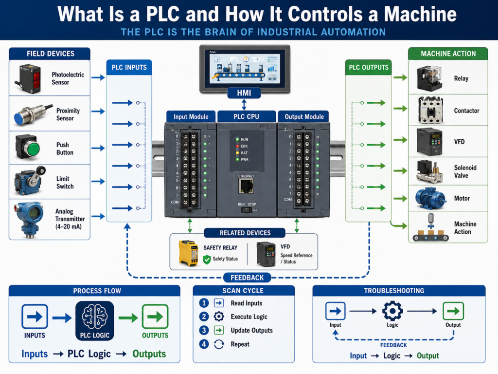
The basic PLC control path is:
Inputs → PLC Logic → OutputsOr from the machine point of view:
Field Devices → PLC → Machine ActionExample:
Photoeye detects a box
        ↓
PLC input turns ON
        ↓
PLC logic evaluates the condition
        ↓
PLC output turns ON
        ↓
Conveyor motor or solenoid operates
The PLC does not work alone.
It depends on the complete automation system:
Sensors
Push buttons
Limit switches
Transmitters
PLC input modules
PLC CPU
PLC output modules
Relays
Contactors
VFDs
Solenoids
Motors
HMI
SCADA
Industrial network
2. Why PLCs Are Used in Industry
PLCs are used because they are reliable, flexible, and designed for industrial environments.
Compared to a normal office computer, a PLC is built to handle:
Electrical noise
Vibration
Temperature variation
Continuous operation
Industrial I/O signals
Machine control
Fast scan cycles
Harsh environments
A PLC can replace large relay-based control systems with programmable logic.
Instead of rewiring many relays every time the sequence changes, the program can be modified.
This makes PLCs very powerful for automation.
3. Main Parts of a PLC System
A PLC system may include several parts.
CPU
The CPU is the brain of the PLC.
It:
Stores the program
Executes logic
Reads input data
Controls output data
Communicates with other devices
Handles diagnostics
The CPU is where the control decisions happen.
Power Supply
The PLC power supply provides power to the PLC chassis or controller.
This is different from the 24 VDC field power used for sensors and outputs.
Some systems have:
PLC rack power supply
24 VDC control power supply
Field device power supply
I/O module field power
A technician must understand which power supply feeds what.
Input Modules
Input modules receive signals from field devices.
Examples:
Start push button
Stop push button
Photoeye
Proximity sensor
Limit switch
Pressure switch
Overload contact
VFD running feedback
Safety relay status
Input modules tell the PLC what is happening in the real world.
Output Modules
Output modules send commands from the PLC to field devices.
Examples:
Relay coil
Solenoid valve
Pilot light
Stack light
Contactor coil
VFD start input
Alarm horn
Motor starter relay
Output modules allow the PLC to control the machine.
Communication Modules
Communication modules allow the PLC to talk to other devices.
Examples:
HMI
SCADA
VFDs
Remote I/O
Servo drives
Robots
Vision systems
Barcode scanners
Other PLCs
Industrial switches
Common industrial networks include:
EtherNet/IP
Profinet
Modbus TCP
DeviceNet
ControlNet
Profibus
Serial communication
4. Inputs: How the PLC Sees the Machine
Inputs are signals coming into the PLC.
They tell the PLC the status of the machine.
Examples:
Start button pressed
Stop button healthy
Box present
Door closed
Cylinder extended
Tank level high
Motor overload healthy
VFD ready
Pressure OK
Safety relay reset
The PLC reads these input states and uses them in the logic.
Example:
If Start button is pressed
AND safety is healthy
AND no fault is active
THEN start conveyor
Inputs are the PLC’s information from the real world.
5. Outputs: How the PLC Controls the Machine
Outputs are commands going out of the PLC.
They tell devices what to do.
Examples:
Turn ON conveyor motor
Energize solenoid valve
Start pump
Open valve
Turn ON stack light
Reset VFD fault
Sound alarm horn
Enable machine sequence
The PLC output may not directly power the final load.
Often it controls an intermediate device.
Example:
PLC Output
    ↓
Interposing Relay
    ↓
Contactor Coil
    ↓
Motor Starter
    ↓
Motor Runs
The PLC output is the command.
The field device performs the action.
6. PLC Logic
PLC logic is the program that makes decisions.
The logic decides when outputs should turn ON or OFF based on input conditions, internal bits, timers, counters, faults, modes, permissives, and interlocks.
Common logic instructions include:
XIC
XIO
OTE
OTL
OTU
TON
TOF
CTU
RES
MOV
EQU
LES
GRT
ONS
A simple ladder logic example:
Start PB + Stop OK + No Fault = Motor Run CommandIn ladder style:
Start_PB     Stop_OK     No_Fault        Motor_Run
---| |---------| |---------| |--------------( )---
This means the motor run command turns ON only when all required conditions are true.
7. The PLC Scan Cycle
A PLC works in a continuous loop called the scan cycle.
A simplified scan cycle is:
1. Read inputs
2. Execute program logic
3. Update outputs
4. Perform communication and diagnostics
5. Repeat
This happens very fast, usually many times per second.
Step 1 — Read Inputs
The PLC reads the status of input modules.
Example:
Start_PB = ON
Stop_PB = OK
Photoeye = OFF
Overload_OK = ON
Step 2 — Execute Logic
The PLC executes the program using the input data and internal logic.
Example:
If Start_PB and Overload_OK and No_Fault are true,
turn ON Motor_Run_Command.
Step 3 — Update Outputs
The PLC sends output commands to the output modules.
Example:
Motor_Output = ON
Solenoid_Output = OFF
Stack_Light_Green = ON
Step 4 — Repeat
The PLC repeats the scan continuously.
This is why logic can react quickly to changing machine conditions.
8. Discrete I/O vs Analog I/O
PLCs work with both discrete and analog signals.
Discrete I/O
Discrete signals are ON or OFF.
Examples:
Photoeye ON/OFF
Limit switch ON/OFF
Push button pressed/not pressed
Relay energized/not energized
Discrete input:
0 or 1
FALSE or TRUE
OFF or ON
Analog I/O
Analog signals represent variable measurements.
Examples:
Pressure = 72 PSI
Level = 65%
Temperature = 180°F
Flow = 125 GPM
Speed reference = 45 Hz
Analog input:
4–20 mA
0–10 VDC
RTD
Thermocouple
Raw counts
Engineering units
A PLC uses analog values for process control, monitoring, alarms, and setpoints.
9. PLC Memory and Tags
In modern PLCs, signals are stored as tags or addresses.
Examples of tags:
Start_PB
Stop_PB_OK
PE_Box_Present
Motor_Run_Cmd
Motor_Running_FB
Tank_Level_Pct
Pressure_PSI
Alarm_HighPressure
Fault_MotorOL
Older PLCs may use address-based memory.
Examples:
I:1/0
I:1/1
O:2/0
B3:0/0
N7:0
T4:0
C5:0
Tag-based systems are easier to read because the names describe the function.
Example:
Motor_Run_Commandis clearer than:
B3:2/7Good tag names help technicians troubleshoot faster.
10. PLC and HMI Relationship
The HMI allows the operator to interact with the PLC.
The HMI may display:
Machine status
Alarms
Faults
Motor status
Sensor status
Recipes
Setpoints
Manual controls
Production counts
Trends
The HMI reads and writes PLC tags.
Example:
Operator presses Start on HMI
        ↓
HMI writes Start_Request tag
        ↓
PLC sees Start_Request
        ↓
PLC checks logic
        ↓
PLC starts machine if conditions are safe
The HMI does not usually control the machine directly.
The PLC logic should decide what is allowed.
11. PLC and VFD Relationship
A PLC often controls VFDs.
The PLC may send:
Start command
Stop command
Speed reference
Direction command
Fault reset
The VFD may send back:
Ready status
Running feedback
Faulted status
Fault code
Output frequency
Motor current
At speed status
Communication may be hardwired or network-based.
Hardwired example:
PLC output → VFD start input
VFD relay output → PLC running feedback
Network example:
PLC ↔ EtherNet/IP ↔ VFDThe PLC command is not enough.
The PLC should also verify VFD feedback.
12. PLC and Safety Systems
Safety systems may include:
E-stops
Safety relays
Safety PLCs
Light curtains
Guard switches
Safety scanners
Safety mats
Two-hand controls
A standard PLC may monitor safety status, but safety functions should be handled by safety-rated devices.
Example:
E-stop pressed
     ↓
Safety relay drops
     ↓
Motor enable removed
     ↓
PLC receives safety status input
     ↓
HMI displays safety fault
Important concept:
Safety removes dangerous energy.
PLC displays and reacts to safety status.
13. Basic PLC Troubleshooting Method
When troubleshooting PLC-controlled equipment, think:
Input → Logic → OutputThis is one of the most important methods for technicians.
Input
Ask:
Is the PLC seeing the input?
Is the input LED ON?
Is the online tag changing?
Is the field sensor working?
Logic
Ask:
Is the logic allowing the output?
Are permissives true?
Are interlocks clear?
Is a fault latched?
Is the correct mode selected?
Output
Ask:
Is the PLC output ON?
Is voltage leaving the output module?
Is the relay energizing?
Is the solenoid or contactor receiving voltage?
Is the field device working?
This method prevents guessing.
14. Example: Conveyor Does Not Start
Problem:
Operator presses Start, but conveyor does not run.Troubleshooting path:
Step 1 — Check input
Does PLC see Start button?
Does HMI Start_Request turn ON?
Is Stop button healthy?
Is E-stop healthy?
Step 2 — Check logic
Are all permissives true?
Is Auto mode selected?
Is overload healthy?
Is VFD ready?
Is downstream conveyor ready?
Is any fault active?
Step 3 — Check output
Does PLC turn ON conveyor output?
Does relay energize?
Does VFD receive run command?
Does motor starter pull in?
Step 4 — Check feedback
Does motor running feedback turn ON?
Does VFD running bit turn ON?
Does conveyor move?
This is professional troubleshooting.
15. Common PLC Faults and Issues
Common PLC-related issues include:
Input not changing
Output not turning ON
Wrong tag used
Faulted I/O module
PLC in Program mode
PLC communication fault
Forces enabled
Routine not being scanned
Wrong scaling
Latched fault not reset
Bad field wiring
Bad input common
Bad output fuse
HMI tag mismatch
Important:
Many “PLC problems” are actually field wiring, sensor, power, relay, VFD, or mechanical problems.
The PLC is only one part of the control system.
16. Good PLC Program Structure
A professional PLC program should be organized.
A clean structure may include:
Input Buffering
Mode Selection
Requests
Permissives
Interlocks
Command Logic
Fault Logic
Alarm Logic
Output Buffering
HMI Status
This structure makes troubleshooting easier.
Example:
Raw Input → Buffered Input → Logic → Command → Output → Feedback → Fault/AlarmThe goal is not only to make the machine work.
The goal is to make the program understandable, maintainable, and easy to troubleshoot.
17. Common Mistakes New Technicians Make
Mistake 1 — Blaming the PLC first
Always check power, inputs, outputs, wiring, fuses, relays, and field devices.
Mistake 2 — Looking only at the HMI
The HMI may not show the full logic condition.
Go online with the PLC when needed.
Mistake 3 — Ignoring the input LED
The input LED is a fast way to know if the PLC module sees the field signal.
Mistake 4 — Assuming output LED means the device energized
The PLC output LED does not prove the field load received voltage.
Mistake 5 — Not checking feedback
A command is not proof.
Always verify feedback when available.
Mistake 6 — Not checking if a routine is scanned
Logic inside a routine that is not called will not execute.
18. Technician Checklist
When troubleshooting a PLC-controlled machine, verify:
PLC is in RUN mode
No processor fault active
I/O modules healthy
Communication healthy
Input LED changes
Online input tag changes
Buffered input changes
Logic conditions are true
Correct mode is selected
Permissives are true
Interlocks are clear
Faults are reset
Output tag turns ON
Output LED turns ON
Output voltage reaches device
Relay/contactor/solenoid operates
Feedback returns to PLC
HMI displays correct status
Root cause is documented
Final Thoughts
A PLC is the center of many industrial automation systems.
It reads inputs, executes logic, and controls outputs.
But the PLC is not the entire system.
It depends on sensors, field wiring, power supplies, I/O modules, relays, VFDs, safety devices, HMIs, SCADA, and industrial networks.
The basic idea is simple:
Inputs → PLC Logic → OutputsBut real industrial troubleshooting requires a deeper understanding:
Field Device → PLC Input → Program Logic → PLC Output → Field Device → FeedbackA strong automation technician does not just look at the PLC program.
They follow the complete control path.
They verify the input.
They analyze the logic.
They check the output.
They confirm feedback.
They find the root cause.
The PLC makes the decision, but the machine only works when the entire control path is healthy.