22. Permissives vs Interlocks
In industrial automation, two words appear constantly in PLC logic:
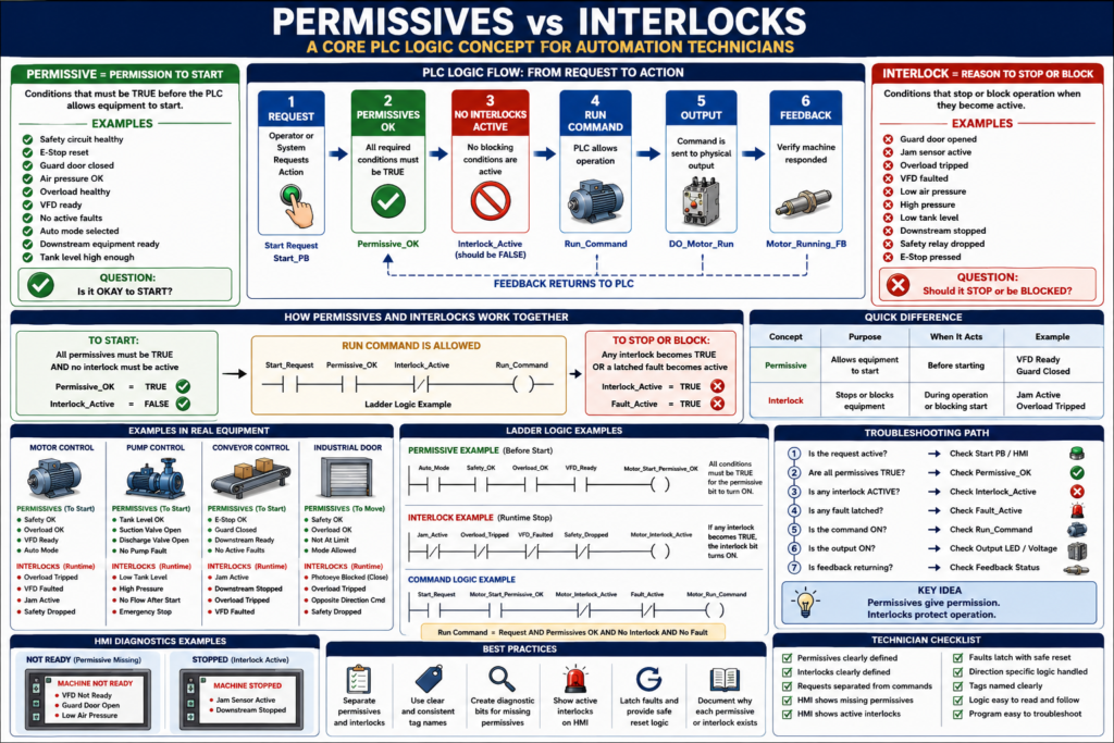
Permissive
Interlock
They are related, but they are not exactly the same.
Understanding the difference helps automation technicians troubleshoot faster, read ladder logic better, and design more professional PLC programs.
A machine may not start because a permissive is missing.
A machine may stop while running because an interlock became active.
Both are used to protect the machine, the process, the product, and sometimes the operator.
A simple way to remember:
Permissives allow equipment to start.
Interlocks stop or block equipment when a condition becomes unsafe or invalid.
1. What Is a Permissive?
A permissive is a condition that must be true before the PLC allows an action to start.
Simple definition:
Permissive = Permission to startExamples:
Safety circuit healthy
E-stop reset
Guard door closed
Air pressure OK
Overload healthy
VFD ready
No active fault
Auto mode selected
Downstream equipment ready
Tank level high enough
A permissive answers this question:
Is it okay to start?If the answer is no, the PLC should not allow the command.
2. What Is an Interlock?
An interlock is a condition that stops, blocks, or prevents operation when something becomes unsafe, invalid, or not ready.
Simple definition:
Interlock = Reason to stop or block operationExamples:
Guard door opened
E-stop pressed
Jam sensor active
Overload tripped
VFD faulted
Low air pressure
High pressure
Low tank level
Downstream conveyor stopped
Safety relay dropped
An interlock answers this question:
Should this equipment be stopped or blocked now?If the answer is yes, the PLC should remove or prevent the command.
3. The Simple Difference
| Concept | Main Purpose | Question It Answers |
|---|---|---|
| Permissive | Allows equipment to start | “Is it okay to start?” |
| Interlock | Stops or blocks equipment | “Should it stop or be blocked?” |
Another simple way:
Permissive = before starting
Interlock = during operation or blocking operation
In real programs, the same condition may appear in both permissive and interlock logic.
Example:
Air pressure OK = permissive to start
Air pressure lost while running = interlock to stop
4. Example: Motor Start Permissives
Before starting a motor, the PLC may check:
Safety_OK
Overload_OK
VFD_Ready
Auto_Mode
No_Motor_Fault
Downstream_Ready
Logic concept:
Motor_Start_Request
AND Safety_OK
AND Overload_OK
AND VFD_Ready
AND Auto_Mode
AND No_Motor_Fault
AND Downstream_Ready
= Motor_Run_Command
If any permissive is false, the motor should not start.
Example:
Motor_Start_Request = ON
VFD_Ready = OFF
Result:
Motor_Run_Command = OFFThe operator requested the motor, but the PLC did not allow it.
That is permissive logic.
5. Example: Motor Runtime Interlocks
While the motor is running, the PLC may monitor:
Overload_Tripped
VFD_Faulted
Safety_Dropped
Jam_Active
Downstream_Stopped
High_Pressure
Logic concept:
If any interlock becomes active,
remove Motor_Run_Command or Motor_Output.
Example:
Motor is running
Jam_Active turns ON
PLC stops motor
HMI displays jam fault or interlock message
That is interlock logic.
6. Permissive Missing vs Interlock Active
This difference is very useful in troubleshooting.
Permissive Missing
The equipment never starts.
Example:
Operator presses Start.
Motor does not run.
Possible reason:
Start permissive is not satisfied.Example HMI message:
Motor Not Ready: VFD Not ReadyInterlock Active
The equipment may start, but then it stops or remains blocked because a condition becomes active.
Example:
Motor starts.
Jam sensor turns ON.
Motor stops.
Example HMI message:
Motor Stopped: Jam Interlock ActiveA good HMI should help separate these two conditions.
7. Why Separating Them Matters
Some PLC programs mix permissives, interlocks, faults, alarms, and commands all in one rung.
That may work, but it becomes hard to troubleshoot.
Better structure:
Permissive Logic:
Are all start conditions OK?

Interlock Logic:
Is anything blocking or stopping operation?

Command Logic:
If request is active, permissives are OK, and no interlock is active, then command equipment.
This structure is easier to read and troubleshoot.
Example:
MTR1_Start_Permissive_OK
MTR1_Interlock_Active
MTR1_Run_Command
Now a technician can quickly see:
Is the motor not starting because permissive is false?
Or is it blocked because an interlock is active?
8. Recommended PLC Structure
A clean structure may look like this:
1. Input Buffering
2. Requests
3. Permissives
4. Interlocks
5. Commands
6. Feedback
7. Faults
8. Outputs
9. HMI Status
For permissives and interlocks:
Permissive_OK = all required start conditions are true
Interlock_Active = any blocking condition is true
Then command logic becomes simple:
Start_Request
AND Permissive_OK
AND NOT Interlock_Active
AND NOT Fault_Active
= Run_Command
This is much easier than putting everything into one long rung.
9. Example: Conveyor Logic
Start Permissives
EStop_OK
Guard_Closed
Overload_OK
VFD_Ready
Auto_Mode
Downstream_Ready
No_Conveyor_Fault
Combined bit:
Conv_Start_Permissive_OKRuntime Interlocks
Jam_Active
Guard_Open
Overload_Tripped
VFD_Faulted
Downstream_Stopped
Safety_Dropped
Combined bit:
Conv_Interlock_ActiveCommand Logic
Conv_Start_Request
AND Conv_Start_Permissive_OK
AND NOT Conv_Interlock_Active
= Conv_Run_Command
Output Logic
Conv_Run_Command
AND NOT Conv_Fault_Active
= DO_Conv_Run
This layout is clean, readable, and technician-friendly.
10. Example: Pump Logic
A pump may require different permissives and interlocks.
Pump Start Permissives
Tank_Level_OK
Suction_Valve_Open
Discharge_Valve_Open
Pump_Overload_OK
VFD_Ready
No_Pump_Fault
Auto_Mode
Pump Interlocks
Tank_Level_Low
Discharge_Pressure_High
Pump_Overload_Tripped
VFD_Faulted
No_Flow_After_Start
Emergency_Stop
Command Concept
Pump_Start_Request
AND Pump_Start_Permissive_OK
AND NOT Pump_Interlock_Active
= Pump_Run_Command
If tank level is too low, the pump should not start or should stop to protect the pump from running dry.
11. Example: Door Control Logic
For an industrial door, permissives and interlocks may be directional.
Open Permissives
Safety_OK
Motor_Overload_OK
Not_Fully_Open
No_Door_Fault
Open_Mode_Allowed
Close Permissives
Safety_OK
Motor_Overload_OK
Not_Fully_Closed
PhotoEye_Clear
No_Door_Fault
Close_Mode_Allowed
Close Interlocks
PhotoEye_Blocked
Safety_Dropped
Overload_Tripped
Close_Limit_Fault
Opposite_Direction_Command
This matters because a door may be allowed to open but not allowed to close.
Example:
Photoeye blockedResult:
Door close command blocked
Door open command may still be allowed
This is good industrial logic.
12. Interlock vs Fault
This can also confuse technicians.
An interlock may block operation, but it may not always be a latched fault.
Interlock
Condition exists right now and blocks operation.Example:
Guard door openWhen the guard closes, the interlock may clear automatically.
Fault
Abnormal condition that may latch and require reset.Example:
Motor commanded ON but feedback missing after 3 seconds.A fault usually needs:
Detection
Latch
Correction
Reset
HMI message
Simple difference:
Interlock = active blocking condition
Fault = detected abnormal event, often latched
Some interlocks can create faults if they occur during operation.
Example:
Low air pressure active = interlock
Low air pressure while running for 5 seconds = fault
13. Interlock vs Alarm
An alarm informs the operator.
An interlock blocks operation.
Example:
Low air pressure warning = alarm
Air pressure too low to operate = interlock
Another example:
Tank level low warning = alarm
Tank level critically low = pump interlock
Simple difference:
Alarm = information
Interlock = action/blocking
A good system may have both.
14. HMI Diagnostics for Permissives and Interlocks
A good HMI should not only say:
Machine Not ReadyThat message is too general.
Better HMI diagnostics:
Machine Not Ready:
- Guard Door Open
- VFD Not Ready
- Low Air Pressure
For interlocks:
Machine Stopped:
- Jam Sensor Active
- Downstream Conveyor Stopped
This helps operators and technicians respond faster.
A strong PLC program can create HMI status bits like:
MTR1_NotReady_VFD
MTR1_NotReady_Overload
MTR1_Interlock_Jam
MTR1_Interlock_Safety
MTR1_Interlock_Downstream
This makes the HMI useful for troubleshooting.
15. PLC Troubleshooting Method
When equipment does not start:
1. Is the request active?
2. Are all permissives true?
3. Is any interlock active?
4. Is any fault latched?
5. Is the command turning ON?
6. Is the output turning ON?
7. Is feedback returning?
When equipment starts and then stops:
1. Did a fault latch?
2. Did an interlock become active?
3. Did feedback fail?
4. Did a safety condition drop?
5. Did a permissive disappear while running?
6. Did the sequence move to a different state?
This method keeps troubleshooting logical.
16. Common Mistakes
Mistake 1 — Mixing everything into one rung
Long rungs with requests, permissives, interlocks, faults, and outputs can work, but they are hard to troubleshoot.
Mistake 2 — Not creating diagnostic bits
If there is no clear Permissive_OK or Interlock_Active bit, the technician must inspect many conditions manually.
Mistake 3 — Treating all interlocks as faults
Some conditions should clear automatically when corrected. Others should latch as faults.
Mistake 4 — Not showing missing permissives on the HMI
Operators need to know why the machine is not ready.
Mistake 5 — Using unsafe reset logic
A reset should not clear a fault if the unsafe condition still exists.
Mistake 6 — Not considering direction-specific permissives
Some machines need different permissives for open, close, forward, reverse, fill, drain, extend, and retract.
17. Best Practices
Use these practices:
Create clear permissive bits.
Create clear interlock bits.
Separate requests from commands.
Separate permissives from interlocks.
Use fault latches for abnormal events.
Use HMI messages for missing permissives.
Use HMI messages for active interlocks.
Use meaningful tag names.
Document why each permissive or interlock exists.
Use direction-specific logic where needed.
Avoid duplicate outputs.
Keep command logic simple.
Example naming:
MTR1_StartPerm_OK
MTR1_Interlock_Active
MTR1_Run_Cmd
MTR1_Fault_Active
18. Technician Checklist
When reviewing permissive/interlock logic, ask:
What conditions allow this equipment to start?
What conditions should stop it while running?
Which conditions should latch as faults?
Which conditions should only alarm?
Are missing permissives shown on the HMI?
Are active interlocks shown on the HMI?
Are permissives and interlocks separated?
Are requests separated from commands?
Are tags named clearly?
Is reset logic safe?
Are direction-specific conditions handled?
Final Thoughts
Permissives and interlocks are core concepts in professional PLC logic.
They help make machines safer, more reliable, and easier to troubleshoot.
A permissive answers:
Is it okay to start?An interlock answers:
Should operation be stopped or blocked?When these concepts are separated clearly, the program becomes easier to read.
The HMI becomes more useful.
Troubleshooting becomes faster.
Operators understand why the machine is not ready.
Technicians can find the root cause more efficiently.
Permissives give permission. Interlocks protect operation.
That simple idea is one of the foundations of industrial PLC programming.