21. Professional PLC Program Structure
A PLC program should do more than make a machine run.
A professional PLC program should be:
Organized
Readable
Troubleshooting-friendly
Safe
Consistent
Expandable
Maintainable
In real industrial environments, machines are modified, maintained, repaired, upgraded, and troubleshot by different technicians and engineers over many years.
That means the program must be easy to understand.
A program that works but is disorganized can create serious problems:
Hard to troubleshoot
Hard to modify
Hard to train new technicians
Hard to find faults
Hard to follow machine sequence
Easy to create duplicate outputs
Easy to miss interlocks
Easy to hide unsafe conditions
A professional structure helps the technician understand the logic step by step.
1. Why PLC Structure Matters
When a machine stops, the technician needs to find the problem quickly.
A good PLC structure helps answer questions like:
Is the PLC seeing the input?
Is the request active?
Are permissives true?
Is an interlock blocking operation?
Is a fault latched?
Is the command turning ON?
Is the output energizing?
Is feedback returning?
What should the HMI display?
Without structure, the technician may have to search through many rungs randomly.
With structure, the program has a logical flow:
Inputs → Requests → Permissives → Interlocks → Commands → Outputs → Feedback → Faults → HMIThis makes troubleshooting faster and more professional.
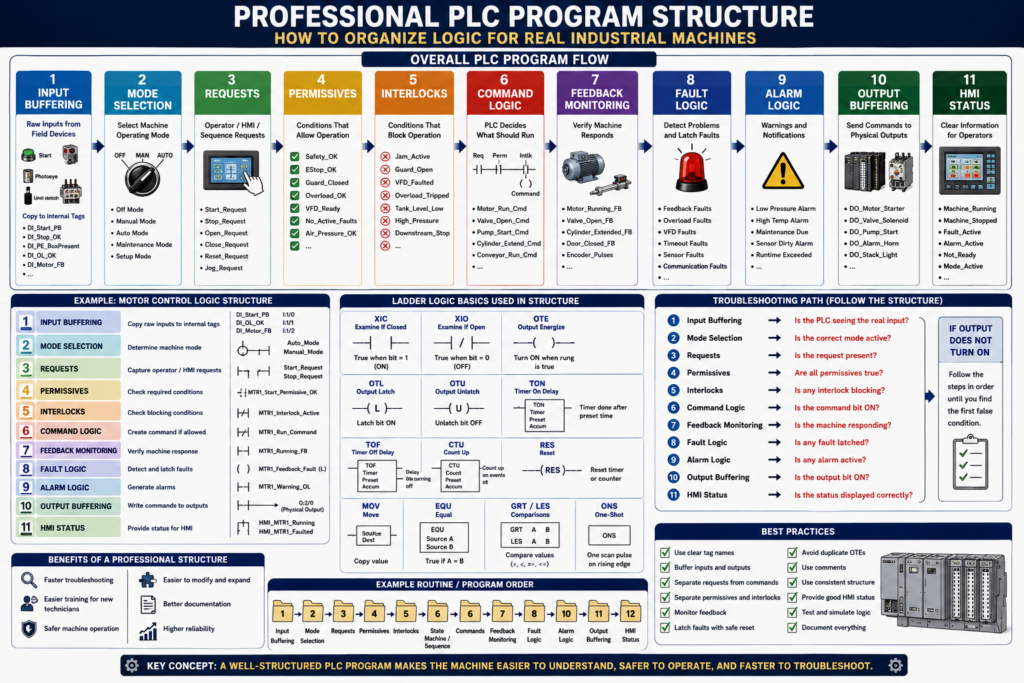
2. Basic Professional PLC Flow
A clean industrial PLC program often follows this type of structure:
1. Input Buffering
2. Mode Selection
3. Requests
4. Permissives
5. Interlocks
6. Command Logic
7. Feedback Monitoring
8. Fault Logic
9. Alarm Logic
10. Output Buffering
11. HMI Status
The exact structure may change depending on the machine, company standard, or PLC platform.
But the idea is the same:
Separate different types of logic so the program is easier to understand.
3. Input Buffering
Input buffering means copying raw physical inputs into internal tags.
Example:
Raw Input: Local:1:I.Data.0
Buffered Tag: DI_Start_PB
Or in RSLogix 500 style:
Raw Input: I:1/0
Buffered Bit: B3:0/0 Start_PB
Why buffer inputs?
Cleaner tag names
Easier troubleshooting
Easier simulation
One place to invert signals if needed
One place to map field inputs
Better HMI diagnostics
Less direct use of raw addresses
Example:
DI_Start_PB       = Raw start button input
DI_Stop_OK        = Raw stop circuit healthy input
DI_PE_BoxPresent  = Raw photoeye input
DI_OL_OK          = Raw overload healthy input
DI_Motor_FB       = Raw motor feedback input
A technician should be able to go to the input buffering section and quickly see if the PLC is receiving the real field signal.
4. Mode Selection
Many machines have multiple modes.
Common modes:
Off
Manual
Auto
Jog
Maintenance
Setup
Clean-in-place
Faulted
Stopped
Mode logic determines how the machine is allowed to operate.
Example:
Auto_Mode
Manual_Mode
Maintenance_Mode
Mode selection may come from:
HMI selector
Physical selector switch
Key switch
Recipe setting
Supervisor access
Machine state
Good mode logic prevents confusion.
Example:
Auto commands should only work in Auto Mode.
Manual jog commands should only work in Manual or Maintenance Mode.
No motion should occur in Off Mode.
Mode logic should be clear and centralized.
5. Requests
A request is when an operator, HMI, PLC sequence, or another system asks for something to happen.
Examples:
Start_Request
Stop_Request
Open_Request
Close_Request
Reset_Request
Auto_Start_Request
Jog_Forward_Request
Pump_Start_Request
Valve_Open_Request
A request is not the same as a command.
Request = what the operator or sequence wants
Command = what the PLC allows after checking conditions
Example:
Operator presses Start on HMI
        ↓
Start_Request turns ON
        ↓
PLC checks permissives and interlocks
        ↓
Run_Command turns ON only if allowed
This separation is very important.
6. Permissives
A permissive is a condition that must be true before equipment is allowed to start.
Simple definition:
Permissive = permission to startExamples:
Safety_OK
EStop_OK
Guard_Door_Closed
Overload_OK
VFD_Ready
Air_Pressure_OK
No_Active_Faults
Downstream_Ready
Auto_Mode_Selected
Example motor permissive:
Motor_Start_Permissive =
Safety_OK
AND Overload_OK
AND VFD_Ready
AND No_Motor_Fault
AND Auto_Mode
If one permissive is missing, the motor should not start.
Good programs often create a single permissive bit:
MTR1_Start_Permissive_OKThis makes the command logic easier to read.
7. Interlocks
An interlock is a condition that stops or blocks operation while the machine is running.
Simple definition:
Interlock = reason to stop or block operationExamples:
Jam_Active
Guard_Door_Open
Overload_Tripped
VFD_Faulted
Low_Air_Pressure
Downstream_Stopped
Tank_Level_Low
Pressure_High
Safety_Dropped
Permissive and interlock are related, but they are not exactly the same.
Permissive = required before start
Interlock = stops or blocks operation
Example:
Start permissive:
Air pressure must be OK before starting.

Runtime interlock:
If air pressure drops while running, stop the machine.
Keeping permissives and interlocks separate makes troubleshooting easier.
8. Command Logic
Command logic is where the PLC decides what should actually run.
Examples:
Motor_Run_Command
Valve_Open_Command
Cylinder_Extend_Command
Conveyor_Run_Command
Pump_Start_Command
Door_Open_Command
A command should be based on:
Request
Mode
Permissives
Interlocks
Faults
Sequence step
Manual conditions
Safety status
Example:
Start_Request
AND Auto_Mode
AND Motor_Start_Permissive_OK
AND NOT Motor_Interlock_Active
= Motor_Run_Command
Important:
The command is what the PLC allows, not just what the operator requested.
9. Feedback Monitoring
Feedback proves that the real machine responded to the command.
Examples:
Motor running feedback
VFD running status
Contactor auxiliary contact
Valve open limit switch
Cylinder extended sensor
Door fully open limit switch
Encoder pulses
Flow switch
Pressure increase
Feedback monitoring compares command vs real-world response.
Example:
Motor_Run_Command = ON
Motor_Running_Feedback should turn ON
If feedback does not appear within a time limit, the PLC can generate a fault.
Feedback is what makes the program more diagnostic and professional.
10. Fault Logic
Fault logic detects abnormal conditions.
Examples:
Motor feedback missing
Overload tripped
VFD fault active
Cylinder failed to extend
Valve failed to open
Door failed to close
Low air pressure
High pressure
Analog signal fault
Communication fault
Faults usually stop or prevent operation.
A professional fault structure may include:
Fault detection condition
Fault timer if needed
Fault latch
Fault reset condition
HMI fault message
Fault summary bit
Example:
Motor_Run_Command ON
AND Motor_Feedback OFF
FOR 3 seconds
= Latch Motor_Feedback_Fault
Faults should normally be latched so technicians can see what happened.
11. Alarm Logic
Alarms inform the operator or technician.
Alarms may or may not stop the machine.
Examples:
Low air pressure warning
Maintenance due
High temperature warning
Low tank level warning
VFD warning
Sensor dirty warning
Runtime exceeded
Simple difference:
Fault = stops or prevents operation
Alarm = informs or warns
A good program separates faults and alarms.
This helps operators understand what requires immediate action and what is only a warning.
12. Output Buffering
Output buffering means using internal command bits first, then mapping them to physical outputs in one organized section.
Example:
Internal command: DO_Motor_Run_Cmd
Physical output: Local:2:O.Data.0
Or RSLogix 500 style:
B3:10/0 Motor_Run_Cmd → O:2/0 Motor Starter OutputWhy output buffering helps:
Keeps physical output mapping organized
Prevents scattered physical output coils
Makes simulation easier
Makes troubleshooting easier
Reduces duplicate OTE issues
Centralizes output assignments
A good rule:
Command logic creates internal command bits.
Output buffering writes final commands to physical outputs.
13. HMI Status
HMI status logic prepares clean information for the operator.
The HMI should not have to interpret raw logic everywhere.
The PLC should provide clear status bits and values.
Examples:
Machine_Running
Machine_Stopped
Machine_Faulted
Machine_Ready
Auto_Mode_Active
Manual_Mode_Active
Motor_Running_Status
Valve_Open_Status
Fault_Active
Alarm_Active
Permissive_Missing
Interlock_Active
Good HMI status helps operators and technicians understand the machine faster.
Example:
Bad HMI:
Motor will not start.

Better HMI:
Motor will not start because Overload_OK is false.
The second message is much more useful.
14. Example Professional Motor Logic Structure
For one motor, the structure may look like this:
1. Inputs
DI_MTR1_Start_PB
DI_MTR1_Stop_OK
DI_MTR1_OL_OK
DI_MTR1_FB

2. Requests
MTR1_Start_Request
MTR1_Stop_Request
MTR1_Reset_Request

3. Permissives
MTR1_Start_Permissive_OK

4. Interlocks
MTR1_Interlock_Active

5. Commands
MTR1_Run_Command

6. Feedback
MTR1_Running_Feedback

7. Faults
MTR1_Feedback_Fault
MTR1_Overload_Fault

8. Outputs
DO_MTR1_Starter

9. HMI Status
HMI_MTR1_Running
HMI_MTR1_Faulted
HMI_MTR1_NotReady
This is much easier to troubleshoot than one large rung with everything mixed together.
15. Example Door Control Structure
For an industrial door, the structure may look like this:
Inputs:
DI_Open_PB
DI_Close_PB
DI_Stop_OK
DI_LS_Open
DI_LS_Close
DI_PhotoEye_Clear
DI_Motor_OL_OK
DI_Motor_FB_OK

Requests:
Open_Request
Close_Request
Stop_Request
Reset_Request

Permissives:
Open_Permissive_OK
Close_Permissive_OK

Interlocks:
PhotoEye_Interlock
Overload_Interlock
Opposite_Direction_Interlock

Commands:
Open_Command
Close_Command

States:
Door_State = 0 Idle
Door_State = 10 Opening
Door_State = 20 Fully_Open
Door_State = 30 Closing
Door_State = 40 Fully_Closed
Door_State = 50 Stopped
Door_State = 60 Faulted

Faults:
Open_Feedback_Fault
Close_Feedback_Fault
Overload_Fault
LimitSwitch_Fault

Outputs:
DO_Open_Motor
DO_Close_Motor

HMI:
HMI_Door_Opening
HMI_Door_Closing
HMI_Door_Faulted
HMI_Door_Ajar
This type of organization makes the logic more industrial and easier to expand.
16. Recommended Routine Order
A professional ladder program may use routines in this order:
1. Input_Buffering
2. Mode_Selection
3. Requests
4. Permissives
5. Interlocks
6. State_Machine / Sequence
7. Commands
8. Feedback_Monitoring
9. Fault_Logic
10. Alarm_Logic
11. Output_Buffering
12. HMI_Status
This order follows how the machine thinks:
Read what is happening.
Understand the mode.
Capture what is requested.
Check if it is allowed.
Check what blocks operation.
Decide the sequence.
Create commands.
Verify feedback.
Detect faults.
Display status.
Write outputs.
Some companies place output buffering before HMI status, and some place HMI status last.
The important part is consistency.
17. Why This Helps Troubleshooting
A structured program allows a technician to troubleshoot in order.
Example problem:
Motor does not start.Troubleshooting path:
1. Check input buffering.
2. Check start request.
3. Check mode.
4. Check permissives.
5. Check interlocks.
6. Check fault bits.
7. Check command.
8. Check output.
9. Check feedback.
10. Check HMI status.
Instead of searching randomly, the technician follows the program structure.
18. Common Mistakes in PLC Program Structure
Mistake 1 — Using raw inputs everywhere
Raw input addresses scattered throughout the program make troubleshooting harder.
Mistake 2 — Writing physical outputs in many routines
This can create duplicate output problems.
Mistake 3 — Mixing permissives, interlocks, commands, and faults in one rung
It may work, but it becomes hard to troubleshoot.
Mistake 4 — No clear fault reset logic
Faults should latch and reset only when the condition is corrected.
Mistake 5 — HMI using raw internal bits without clear status logic
The HMI should show meaningful machine status, not confusing raw bits.
Mistake 6 — No comments
Rung comments and tag descriptions are part of professional programming.
19. Best Practices
Use these practices when building or reviewing PLC logic:
Use clear tag names.
Buffer raw inputs.
Buffer physical outputs.
Separate requests from commands.
Separate permissives from interlocks.
Use feedback monitoring.
Latch important faults.
Create clear reset conditions.
Use HMI status bits.
Avoid duplicate OTEs.
Use comments on important rungs.
Group logic by equipment.
Use consistent naming.
Document state values.
Keep logic readable.
The goal is not to make the most compact program.
The goal is to make the most understandable and reliable program.
20. Technician Checklist
When reviewing a PLC program, ask:
Are raw inputs buffered?
Are physical outputs buffered?
Are modes clearly defined?
Are requests separated from commands?
Are permissives grouped?
Are interlocks grouped?
Are faults latched?
Are reset conditions safe?
Is feedback monitored?
Are HMI status bits clear?
Are outputs written in one place?
Are duplicate OTEs avoided?
Are routines called in correct order?
Are tags named clearly?
Are rung comments useful?
Can another technician troubleshoot this quickly?
Final Thoughts
Professional PLC programming is not only about making the machine run.
It is about making the program clear, safe, reliable, and easy to troubleshoot.
A good structure helps technicians understand the logic path:
Inputs → Requests → Permissives → Interlocks → Commands → Outputs → Feedback → Faults → HMIWhen the program is organized, troubleshooting becomes much easier.
A technician can follow the logic step by step instead of guessing.
A professional PLC program should explain the machine’s behavior clearly enough that another technician can troubleshoot it under pressure.
That is the difference between logic that simply works and logic that belongs in an industrial environment.