20. Ladder Logic Basics for Automation Technicians
Ladder logic is one of the most common programming languages used in industrial automation.
It is used to program PLCs that control machines, conveyors, pumps, valves, motors, packaging equipment, process systems, and many other industrial applications.
For an automation technician, ladder logic is not only about programming.
It is also about troubleshooting.
When a machine stops, faults, or does not behave correctly, the technician often goes online with the PLC and follows the ladder logic to understand:
Is the input ON?
Is the request active?
Are the permissives true?
Is an interlock blocking the command?
Is a fault latched?
Is the output being energized?
Is feedback returning?
The goal is not to memorize every instruction immediately.
The goal is to understand the basic instructions that appear in almost every PLC program.
1. Why Ladder Logic Looks Like Electrical Drawings
Ladder logic was designed to look similar to relay control circuits.
A basic electrical ladder diagram may have:
Power rail → Contacts → CoilLadder logic uses a similar style:
Left rail → Conditions → Output instructionExample:
Start_PB     Stop_OK     Motor_Run
---| |---------| |----------( )---
This means:
If Start_PB is true
AND Stop_OK is true
THEN Motor_Run turns ON.
Ladder logic is read from:
Left to right
Top to bottom
Just like we discussed in the PLC scan cycle.
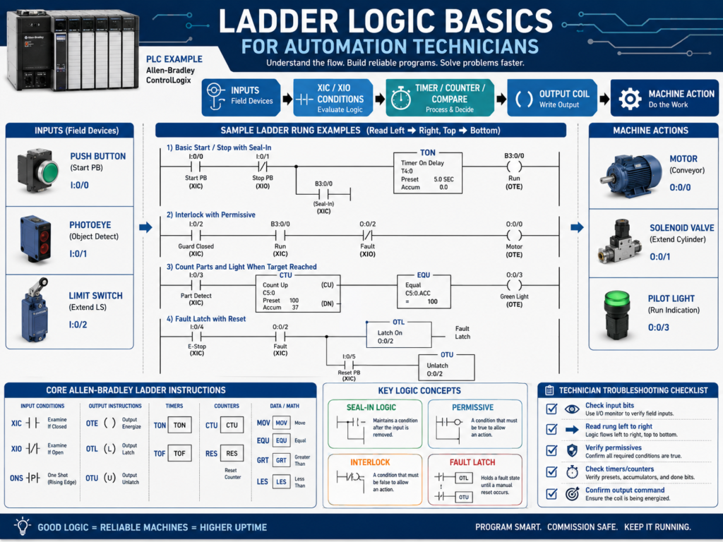
2. XIC — Examine If Closed
The XIC instruction is one of the most common ladder instructions.
Allen-Bradley symbol:
---| |---Meaning:
XIC is true when the bit is ON.Example:
Start_PB
---| |---
This instruction is true when Start_PB = 1.
Common use:
Start button active
Sensor detected
Permissive OK
Motor feedback ON
Auto mode selected
Important:
XIC does not mean the physical device is normally open. It means the PLC bit is ON.
This is a very important distinction.
3. XIO — Examine If Open
The XIO instruction is also very common.
Allen-Bradley symbol:
---|/|---Meaning:
XIO is true when the bit is OFF.Example:
Fault_Active
---|/|---
This instruction is true when Fault_Active = 0.
Common use:
No fault active
Sensor not blocked
Timer not done
Motor not running
Interlock not active
Example:
Start_PB     Fault_Active     Motor_Run
---| |----------|/|------------( )---
Meaning:
Start_PB must be ON
AND Fault_Active must be OFF
THEN Motor_Run turns ON.
4. OTE — Output Energize
The OTE instruction turns a bit ON or OFF based on rung logic.
Allen-Bradley symbol:
---( )---Example:
Motor_Run
---( )---
If the rung is true, Motor_Run turns ON.
If the rung is false, Motor_Run turns OFF.
This is important:
OTE is not latched.It only stays ON while the rung conditions remain true.
Common uses:
Motor command
Solenoid command
Internal status bit
Pilot light command
Alarm horn command
5. OTL and OTU — Latch and Unlatch
Sometimes you need a bit to stay ON even after the original condition goes false.
This is where latch and unlatch instructions are used.
OTL — Output Latch
Allen-Bradley symbol:
---(L)---The OTL turns a bit ON and keeps it ON.
Example:
Motor_Fault
---(L)---
Once latched, the bit stays ON until an unlatch instruction turns it OFF.
OTU — Output Unlatch
Allen-Bradley symbol:
---(U)---The OTU turns a latched bit OFF.
Example:
Motor_Fault
---(U)---
Common use:
Latch a fault when a problem happens.
Unlatch the fault when reset is pressed and condition is corrected.
Example concept:
Motor command ON
AND feedback missing after delay
= latch Motor_Feedback_Fault
Then:
Reset button pressed
AND feedback fault condition cleared
= unlatch Motor_Feedback_Fault
Important:
Latch instructions should be used carefully. Always make sure there is a safe and clear reset condition.
6. TON — Timer On Delay
The TON instruction delays an action until a condition has been true for a certain amount of time.
Common uses:
Debounce sensor
Delay motor feedback fault
Delay alarm
Start sequence step after time
Confirm condition before action
Example:
Motor_Run_Command    TON Motor_FB_Timer  Preset 3 sec
---| |----------------[ TON ]---
Meaning:
If Motor_Run_Command stays true for 3 seconds,
the timer done bit turns ON.
Important timer bits:
.EN = Enable bit
.TT = Timer timing bit
.DN = Done bit
.ACC = Accumulated time
.PRE = Preset time
Example use:
Motor_Run_Command ON
AND Motor_Running_Feedback OFF
FOR 3 seconds
= Motor Feedback Fault
Timers are essential for industrial troubleshooting logic.
7. TOF — Timer Off Delay
The TOF instruction delays turning something OFF.
It keeps the done bit true for a period of time after the rung goes false.
Common uses:
Keep fan running after stop
Delay output off
Prevent short cycling
Maintain signal briefly
Post-purge delay
Example:
Fan_Run_Command    TOF Fan_OffDelay  Preset 10 sec
---| |--------------[ TOF ]---
When the command turns OFF, the timer keeps the output condition active for the preset time.
8. CTU — Count Up
The CTU instruction counts events.
Common uses:
Count boxes
Count bottles
Count cycles
Count rejects
Count machine starts
Count faults
Example:
Box_Detected_OneShot    CTU Box_Counter
---| |------------------[ CTU ]---
Important:
A counter should usually count transitions, not a signal that stays ON for many scans.
That is why one-shots are often used before counters.
Without a one-shot:
Photoeye ON for 1 second
PLC scans many times
Counter may count many times
With a one-shot:
Photoeye changes from OFF to ON
Counter counts once
9. RES — Reset
The RES instruction resets timers or counters.
Common uses:
Reset counter accumulated value
Reset timer accumulated value
Clear count after batch complete
Reset cycle count
Example:
Reset_Counter_PB    RES Box_Counter
---| |--------------[ RES ]---
Use reset instructions carefully, especially in production counters or batch systems.
10. MOV — Move
The MOV instruction copies a value from one location to another.
Common uses:
Move setpoint
Move state value
Move recipe value
Move analog value
Move HMI entry into PLC tag
Set machine mode
Example:
MOV 10 Door_StateMeaning:
Move the value 10 into Door_State.For state machines, MOV is commonly used.
Example:
Door_State = 0   Idle
Door_State = 10  Opening
Door_State = 20  Fully Open
Door_State = 30  Closing
Door_State = 40  Fully Closed
Door_State = 50  Stopped
Door_State = 60  Faulted
The MOV instruction is very useful when building structured PLC sequences.
11. EQU — Equal
The EQU instruction compares two values.
It is true when both values are equal.
Common uses:
Check machine state
Check mode selection
Check recipe number
Check step number
Check fault code
Example:
EQU Door_State 10Meaning:
True when Door_State equals 10.Example use:
If Door_State = 10
Then door is opening.
This is common in state machine logic.
12. GRT, LES, GEQ, LEQ — Comparison Instructions
Comparison instructions are used to compare values.
Common instructions:
GRT = Greater Than
LES = Less Than
GEQ = Greater Than or Equal
LEQ = Less Than or Equal
EQU = Equal
NEQ = Not Equal
Common uses:
Pressure greater than high limit
Tank level less than low limit
Temperature above alarm limit
Speed greater than zero
Weight within tolerance
Analog value out of range
Example:
GRT Pressure_PSI 90Meaning:
True when Pressure_PSI is greater than 90.Example:
LES Tank_Level_Pct 10Meaning:
True when Tank_Level_Pct is less than 10.These instructions are very important for analog instrumentation logic.
13. ONS — One-Shot
The ONS instruction creates a pulse for one scan when a condition changes from false to true.
Common uses:
Count one product
Trigger one event
Toggle a bit
Capture value once
Start a sequence step once
Example:
Photoeye_BoxPresent    ONS    CTU Box_Count
---| |-----------------[ONS]---[CTU]---
Meaning:
When the photoeye first turns ON,
create a one-scan pulse,
then count once.
Without the one-shot, the counter may count multiple times.
A one-shot is very useful when the input stays ON longer than one PLC scan.
14. Seal-In Logic
Seal-in logic is a classic ladder logic pattern.
It allows a momentary Start button to keep a motor command ON after the button is released.
Example concept:
Start_PB OR Motor_Run_Command
AND Stop_OK
AND No_Fault
= Motor_Run_Command
Text representation:
Stop_OK     No_Fault     Start_PB              Motor_Run_Command
---| |--------| |----------| |----------------------( )---
                         |
                         | Motor_Run_Command
                         ---| |---
How it works:
Press Start → Motor_Run_Command turns ON
Motor_Run_Command seals itself ON
Release Start → Motor_Run_Command stays ON
Press Stop or Fault occurs → Motor_Run_Command turns OFF
This is one of the most important ladder patterns to understand.
15. Permissive Logic
A permissive is a condition required before equipment can start.
Example:
Motor can start only if:
- E-stop healthy
- Overload healthy
- Guard closed
- VFD ready
- No active fault
Ladder concept:
Start_Request
AND Safety_OK
AND Overload_OK
AND VFD_Ready
AND No_Fault
= Motor_Run_Command
Permissives are normally used to allow starting.
They make the logic safer and easier to troubleshoot.
16. Interlock Logic
An interlock blocks or stops equipment when a condition becomes unsafe or invalid.
Examples:
Guard door open
Jam sensor active
Overload trips
VFD fault active
Downstream conveyor stopped
Tank level too low
Pressure too high
Simple concept:
If interlock active, stop or block the command.Example:
Motor_Run_Command
AND NOT Jam_Active
AND NOT VFD_Fault
= Motor_Output
In ladder, this may use XIO instructions for interlock bits that must be OFF.
17. Fault Logic
Fault logic detects abnormal conditions and usually latches them.
Example:
Motor command ON
AND feedback OFF
FOR 3 seconds
= Motor Feedback Fault
Typical structure:
1. Detect the condition.
2. Delay if needed.
3. Latch the fault.
4. Stop or block operation.
5. Display fault on HMI.
6. Allow reset only when safe.
Faults are very important for diagnostics.
A good fault message helps the technician find the problem faster.
18. Ladder Logic Troubleshooting Method
When troubleshooting ladder logic, follow the logic path.
Use this method:
1. Find the output or command that is not working.
2. Look at the rung controlling it.
3. Read the rung left to right.
4. Identify which condition is false.
5. Trace that condition back to its source.
6. Check if it is an input, internal bit, timer, fault, or interlock.
7. Verify field device if needed.
8. Correct the root cause.
Example:
Motor_Output does not turn ON.Check:
Is Motor_Run_Command ON?
Is Safety_OK ON?
Is Overload_OK ON?
Is VFD_Ready ON?
Is Fault_Active OFF?
Is Stop_OK ON?
The false condition tells you where to troubleshoot next.
19. Common Mistakes New Technicians Make
Mistake 1 — Thinking XIC means normally open
XIC means the PLC bit is ON.
It does not directly mean the physical device is normally open.
Mistake 2 — Thinking XIO means normally closed
XIO means the PLC bit is OFF.
It does not directly mean the physical device is normally closed.
Mistake 3 — Using the same OTE in multiple rungs
This can create last-rung-wins problems.
Mistake 4 — Counting without a one-shot
A counter may count many times while an input remains ON.
Mistake 5 — Latching faults without reset conditions
Every latched fault needs a proper reset path.
Mistake 6 — Troubleshooting from right to left only
Read the rung left to right, and find the first false condition blocking the output.
20. Technician Checklist
When reading ladder logic, verify:
Input bits
Buffered inputs
XIC/XIO state
Seal-in branches
Permissives
Interlocks
Timers
Timer done bits
Counters
One-shots
Latched faults
Reset logic
Command bits
Output bits
Feedback bits
Duplicate OTEs
Routine scan order
HMI status tags
Final Thoughts
Ladder logic is the language that many PLCs use to control industrial machines.
For automation technicians, understanding ladder logic is essential for troubleshooting.
The most important instructions to learn first are:
XIC
XIO
OTE
OTL
OTU
TON
TOF
CTU
RES
MOV
EQU
GRT
LES
ONS
These instructions appear in real machines every day.
A strong technician does not only look at whether an output is ON or OFF.
They follow the rung.
They check each condition.
They understand the scan cycle.
They separate command from feedback.
They identify permissives and interlocks.
They understand timers, counters, and latches.
They find the false condition blocking the output.
Ladder logic troubleshooting is about following the conditions until you find what is stopping the machine from doing what it should do.
Once you understand the basic instructions, PLC troubleshooting becomes much more logical and much less intimidating.