16. PLC Control of a VFD: Digital Start, Analog Speed, and Feedback (16 of 19)
Introduction
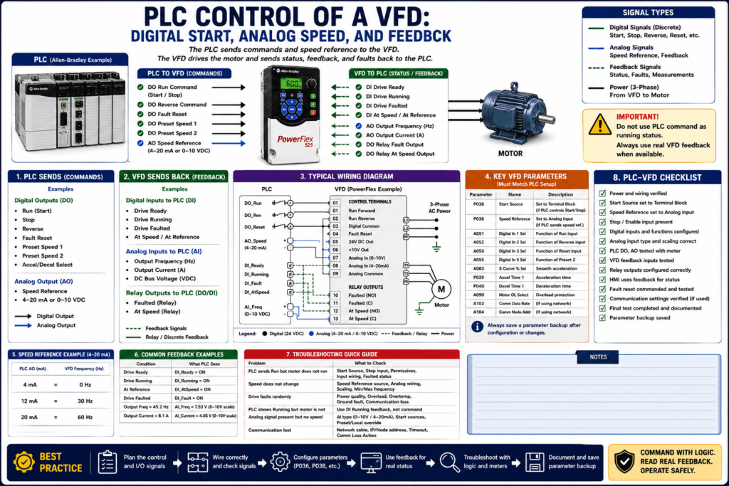
Not every VFD application uses Ethernet/IP, Modbus, PROFIBUS, or network communication. In many real industrial machines, a PLC controls a VFD using simple hardwired signals.
This is one of the most common control methods in the field:
PLC Digital Output → VFD Start / Run Input
PLC Analog Output  → VFD Speed Reference
VFD Relay Output   → PLC Running / Fault / At Speed Feedback
VFD Analog Output  → PLC Speed / Current Feedback
This method is simple, reliable, and easy to troubleshoot when the wiring, parameters, and PLC logic are organized correctly.
The examples in this post use Allen-Bradley PowerFlex drives as a practical reference, but the concepts apply to most industrial VFDs regardless of manufacturer.
Why This Method Is Still Important
Networked VFD control is powerful, but hardwired PLC-to-VFD control is still very common because it is:
Simple
Reliable
Easy to understand
Easy to troubleshoot with a meter
Compatible with many VFD brands
Useful for older machines
Useful when communication is not required
A practical exercise where the PLC provides a digital input to start/stop the motor and controls two speeds of a motor through the VFD, then requires the technician to set acceleration/deceleration, test operation, and record parameters.
That is exactly the field concept: the PLC sends commands, the VFD controls the motor, and the technician verifies the behavior.
1. Basic PLC-to-VFD Signal Types
A VFD controlled by a PLC may use four main signal types:
| Signal Type | Direction | Purpose |
|---|---|---|
| Digital Output | PLC → VFD | Start, Stop, Reverse, Reset, Preset Speed |
| Analog Output | PLC → VFD | Speed reference |
| Digital / Relay Output | VFD → PLC | Running, Faulted, Ready, At Speed |
| Analog Output | VFD → PLC | Output frequency, current, speed feedback |
The VFD training material explains that remote VFD control signals commonly include digital inputs, analog inputs, digital/relay outputs, and analog outputs. Digital inputs can command start, stop, reverse, jog, or speed changes; analog inputs provide speed reference or feedback signals; relay outputs can indicate alarms or speed reached; analog outputs can display current or speed.
2. Digital Start Command from the PLC
The most basic PLC-to-VFD control signal is a digital run command.
Example:
PLC Output ON  → VFD Run Input ON  → Motor Runs
PLC Output OFF → VFD Run Input OFF → Motor Stops
This is usually configured as 2-wire control.
In this setup, the PLC maintains the run command for as long as the motor should run.
Typical PLC Output Tags
VFD_Run_Request
VFD_Run_Permissive
VFD_Run_Command
DO_VFD_Run
A professional structure would be:
Request → Permissives → Command → OutputExample:
Operator_Start_Request
AND Auto_Mode
AND Safety_OK
AND Process_Permissive_OK
AND NOT VFD_Faulted
= VFD_Run_Command
Then:
VFD_Run_Command → DO_VFD_Run3. The VFD Must Be Configured for Terminal Control
The PLC output will not work unless the VFD is configured to accept start commands from the terminal block.
For a PowerFlex-style example:
P036 [Start Source] = Terminal Block / 2-Wire / 3-WirePowerFlex 400 documentation explains that in Auto mode, the start command is defined by P036 [Start Source], while speed reference is defined separately by P038 [Speed Reference].
This is one of the most common troubleshooting problems:
PLC output is ON,
but the drive Start Source is still set to Keypad.
Result:
The drive ignores the PLC command.4. Stop Input and Enable Input
Many VFDs require a Stop or Enable input to be present before the drive can run.
On PowerFlex-style drives, the Stop input is often a required input. The PowerFlex manual start-up checklist specifically says to verify that the Stop input is present, or the drive will not start. It also explains that the sink/source DIP switch must match the control wiring scheme before start-up.
Before blaming the PLC or drive, check:
[ ] Is the Stop input present?
[ ] Is the enable input present, if required?
[ ] Is the factory jumper installed or removed correctly?
[ ] Is the safety/interlock circuit closed?
[ ] Is the drive input status changing?
5. Analog Speed Reference from the PLC
The PLC can control VFD speed using an analog output.
Common analog speed signals:
0–10 VDC
4–20 mA
0–20 mA
The PLC sends a proportional signal, and the VFD converts that signal into a frequency command.
Example:
4 mA  = 0 Hz
12 mA = 30 Hz
20 mA = 60 Hz
Or:
0 VDC  = 0 Hz
5 VDC  = 30 Hz
10 VDC = 60 Hz
The VFD Must Be Configured for Analog Speed
For a PowerFlex-style example:
P038 [Speed Reference] = Analog InputThe PowerFlex manual explains that the speed command can come from different sources and is normally determined by P038 [Speed Reference]. It also notes that digital inputs such as jog, local/remote, communication select, or preset inputs can override the normal speed reference depending on configuration.
This matters because the PLC may be sending a perfect 4–20 mA signal, but the drive may still ignore it if the speed reference is set to keypad, preset speed, or communication.
6. Analog Scaling Example
Suppose the drive is configured:
4–20 mA = 0–60 HzThen the PLC analog output should be scaled so that:
| Desired Speed | PLC Analog Output |
|---|---|
| 0 Hz | 4 mA |
| 15 Hz | 8 mA |
| 30 Hz | 12 mA |
| 45 Hz | 16 mA |
| 60 Hz | 20 mA |
If using 0–10 VDC:
| Desired Speed | PLC Analog Output |
|---|---|
| 0 Hz | 0 VDC |
| 30 Hz | 5 VDC |
| 60 Hz | 10 VDC |
Technician Note
Always verify both sides:
PLC scaling side:
PLC speed command → analog output value

VFD scaling side:
Analog input value → frequency reference
A scaling mismatch can make the motor run too slow, too fast, or not at all.
7. Preset Speeds from the PLC
Instead of analog speed, the PLC may select preset speeds using digital outputs.
Example:
PLC DO 1 → Preset Speed Select 1
PLC DO 2 → Preset Speed Select 2
The VFD stores the actual speed values internally.
Example:
Preset Speed 1 = 30 Hz
Preset Speed 2 = 45 Hz
Preset Speed 3 = 60 Hz
The VFD lab manual includes exercises where a selector switch or PLC chooses between two motor speeds and requires the technician to test operation and record the parameters.
Preset speed control is useful when the machine only needs a few fixed speeds.
8. VFD Running Feedback to the PLC
The PLC should not assume the motor is running just because it sent a run command.
A professional system uses feedback.
Common feedback signals:
VFD_Running_FB
VFD_Faulted_FB
VFD_Ready_FB
VFD_AtSpeed_FB
These may come from VFD relay outputs, transistor outputs, or communication.
A relay output is often a dry contact from the drive to a PLC input.
The VFD training material explains that relay outputs are dry contacts and can be used to indicate alarms, speed reached, or other VFD conditions.
Command vs Feedback
This is very important:
Command = What the PLC requests
Feedback = What the VFD actually reports
Example:
DO_VFD_Run = ON
DI_VFD_Running = OFF
DI_VFD_Faulted = ON
Interpretation:
The PLC is asking the VFD to run, but the drive is faulted.9. Fault Feedback to the PLC
At minimum, the PLC should know when the drive is faulted.
A simple hardwired system may use one relay output:
VFD Fault Relay → PLC Digital InputBetter systems may include:
Drive Ready
Drive Running
Drive Faulted
At Speed
For troubleshooting, the HMI should show clear status:
VFD Ready: Yes/No
VFD Running: Yes/No
VFD Faulted: Yes/No
VFD At Speed: Yes/No
If the system uses only a generic fault contact, the technician may still need to check the HIM/keypad for the actual fault code.
10. Analog Feedback from the VFD
Some drives can send analog feedback back to the PLC.
Common VFD analog outputs:
Output Frequency
Output Current
Output Voltage
Process Feedback
Motor Speed
PowerFlex 400 documentation notes that analog outputs can be selected for voltage or current and can be used for metering or as a speed reference for another drive. It also lists analog output defaults such as output frequency and output current in the control terminal information.
Example:
VFD Analog Output 0–10 VDC = Output Frequency 0–60 HzThen:
| VFD Output Frequency | Analog Feedback |
|---|---|
| 0 Hz | 0 VDC |
| 30 Hz | 5 VDC |
| 60 Hz | 10 VDC |
11. Typical Hardwired PLC-to-VFD Architecture
A simple but strong architecture looks like this:
PLC DO → VFD Run Forward
PLC AO → VFD Analog Speed Reference
VFD Relay Output → PLC DI Running
VFD Relay Output → PLC DI Faulted
VFD Analog Output → PLC AI Output Frequency or Current
Optional signals:
PLC DO → VFD Fault Reset
PLC DO → VFD Reverse
PLC DO → VFD Preset Speed Select
PLC DO → VFD Accel/Decel Profile Select
VFD Relay Output → PLC DI At Speed
VFD Relay Output → PLC DI Ready
PowerFlex 400 control wiring supports digital inputs, programmable digital inputs, analog inputs, relay outputs, analog outputs, and sink/source selection, which shows the type of I/O architecture commonly used for hardwired control.
12. Recommended PLC Logic Structure
A professional PLC program should not directly energize the VFD output from an HMI button.
Bad approach:
HMI_Start_Button → DO_VFD_RunBetter approach:
HMI_Start_Button
        ↓
Run_Request
        ↓
Permissives_OK
        ↓
VFD_Run_Command
        ↓
DO_VFD_Run
        ↓
VFD_Running_Feedback
        ↓
HMI Status
Recommended Sections
1. Input Mapping
2. Mode Selection
3. Requests
4. Permissives
5. Interlocks
6. Commands
7. Faults
8. Outputs
9. Feedback / Status
10. HMI Status
This makes the control system easier to troubleshoot.
13. Example PLC Tags
Inputs from VFD
DI_VFD_Ready
DI_VFD_Running
DI_VFD_Faulted
DI_VFD_AtSpeed
AI_VFD_OutputFreq
AI_VFD_OutputCurrent
Outputs to VFD
DO_VFD_Run
DO_VFD_Reset
DO_VFD_Reverse
DO_VFD_PresetSpeed1
DO_VFD_PresetSpeed2
AO_VFD_SpeedRef
Internal Tags
VFD_Run_Request
VFD_Run_Permissive
VFD_Run_Command
VFD_SpeedRef_Hz
VFD_SpeedRef_Raw
VFD_Fault_Latched
VFD_Feedback_Timeout
VFD_NotRunning_Fault
VFD_AtSpeed_Status
14. Example Ladder Logic Concept
Rung 1 — Run Request
HMI_Start_PB OR Auto_Start_Request → Latch VFD_Run_Request
HMI_Stop_PB OR VFD_Faulted_FB     → Unlatch VFD_Run_Request
Rung 2 — Run Permissive
Safety_OK
AND Auto_Mode
AND Motor_Overload_OK
AND NOT VFD_Faulted_FB
AND Process_Ready
= VFD_Run_Permissive
Rung 3 — VFD Run Command
VFD_Run_Request
AND VFD_Run_Permissive
= VFD_Run_Command
Rung 4 — Physical Output
VFD_Run_Command → DO_VFD_RunRung 5 — Running Feedback Timeout
DO_VFD_Run ON
AND DI_VFD_Running OFF
FOR 3 seconds
= VFD_NotRunning_Fault
This catches a common problem: the PLC commands the drive to run, but the drive never confirms running.
15. Speed Reference Logic
The PLC should calculate and limit the speed reference before sending it to the analog output.
Example:
Operator Speed Setpoint = 45 Hz
Minimum Allowed Speed = 10 Hz
Maximum Allowed Speed = 60 Hz
Final Speed Reference = 45 Hz
If operator enters 80 Hz:
Final Speed Reference = 60 HzIf operator enters 2 Hz:
Final Speed Reference = 10 HzAnalog Output Scaling Concept
Example:
0–60 Hz = 4–20 mAFormula concept:
SpeedRef_Hz → Scale → AnalogOutput_mAPractical values:
0 Hz  = 4 mA
30 Hz = 12 mA
60 Hz = 20 mA
The PLC should also clamp the speed reference to safe limits before writing to the analog output.
16. Fault Reset from PLC
A PLC may send a fault reset command to the VFD.
Recommended approach:
HMI_Reset_PB
AND VFD_Faulted_FB
AND Fault_Reset_Permissive
= DO_VFD_Reset_Pulse
Use a pulse, not a maintained reset.
Example:
Reset pulse = 0.5 secondsDo not repeatedly reset the VFD without identifying the cause.
17. Feedback Timeout Faults
A very useful PLC diagnostic is a feedback timeout.
Examples:
Not Running Fault
Command ON but Running Feedback OFF after 3 secondsPossible causes:
VFD faulted
Stop input missing
Start source wrong
Drive in local mode
PLC output wiring problem
VFD digital input not active
Not At Speed Fault
Run command ON but At Speed feedback OFF after 10 secondsPossible causes:
Speed reference missing
Load too heavy
Drive current limiting
Accel time too long
Wrong speed reference source
This makes the HMI much more useful.
18. HMI Status Recommendations
A good HMI should show:
VFD Commanded: Yes/No
VFD Running Feedback: Yes/No
VFD Faulted: Yes/No
VFD Ready: Yes/No
VFD At Speed: Yes/No
Speed Setpoint: Hz or %
Output Frequency: Hz
Output Current: A
Control Mode: Local/Remote/Auto
Fault Message: If available
Do not show only command status.
Bad HMI label:
Motor Running = DO_VFD_RunBetter HMI label:
Motor Running = DI_VFD_RunningThe HMI should display feedback, not just the command.
19. Troubleshooting: PLC Commands VFD but Motor Does Not Run
Check:
[ ] Is the PLC output ON?
[ ] Is voltage present at the VFD run input?
[ ] Is the VFD Start Source set to terminal block?
[ ] Is Stop/Enable input present?
[ ] Is the drive faulted?
[ ] Is the drive in local mode?
[ ] Is the speed reference present?
[ ] Is the analog signal correct?
[ ] Is the VFD digital input status changing?
[ ] Is the motor connected and mechanically free?
PowerFlex troubleshooting guidance states that if a drive does not start from terminal block inputs, the technician should check control input signals, Start Source configuration, Stop input requirements, and sink/source wiring.
20. Troubleshooting: Motor Runs at Wrong Speed
Check:
[ ] PLC analog output value
[ ] VFD analog input value
[ ] Analog signal type: voltage or current
[ ] P038 / Speed Reference source
[ ] Min/max frequency
[ ] Preset speed inputs
[ ] Local/Remote mode
[ ] Analog scaling in PLC
[ ] Analog scaling in VFD
PowerFlex terminal data warns that only one analog frequency source should be connected at a time; if more than one reference is connected, an undetermined frequency reference can result.
21. Troubleshooting: VFD Fault Feedback Is Wrong
Check:
[ ] Is the relay output wired correctly?
[ ] Is the relay common wired correctly?
[ ] Is the relay output configured for Fault?
[ ] Is the PLC input working?
[ ] Is the HMI reading the correct PLC tag?
[ ] Is the relay NO/NC logic correct?
Do not assume the relay output is configured for the function shown on the drawing. Verify the parameter.
22. Safety Notes
Hardwired PLC control is not automatically safety-rated.
Important distinction:
PLC Stop Command = process control
Safety Relay / STO / E-Stop Circuit = safety function
The VFD lab material warns that VFDs are intended to be commanded by control input signals, and that disconnecting/reapplying VFD output power to the motor should not be used as normal control. It also states that if output isolation is required for emergency stop situations, auxiliary contacts should simultaneously disable the drive run command.
23. Common Mistakes Technicians Should Avoid
[ ] Assuming PLC Run Command means the motor is actually running
[ ] Using command status as HMI running status
[ ] Forgetting to configure Start Source for terminal block
[ ] Forgetting to configure Speed Reference for analog input
[ ] Wrong 0–10 V / 4–20 mA setting
[ ] Wrong analog scaling
[ ] Missing Stop or Enable input
[ ] Wrong SNK/SRC setting
[ ] Relay output configured for wrong status
[ ] No feedback timeout logic
[ ] No parameter backup
[ ] Resetting VFD faults repeatedly from the PLC
[ ] Treating PLC stop as a safety-rated stop
Technician Checklist: PLC Control of a VFD
[ ] Identify control method: hardwired or network.
[ ] Verify Start Source.
[ ] Verify Speed Reference.
[ ] Verify Stop/Enable input.
[ ] Verify SNK/SRC wiring.
[ ] Verify PLC digital output reaches VFD input.
[ ] Verify analog speed signal reaches VFD input.
[ ] Verify analog signal type and scaling.
[ ] Verify VFD relay output functions.
[ ] Verify PLC feedback inputs.
[ ] Verify HMI uses feedback for running status.
[ ] Verify reset command is pulsed.
[ ] Verify feedback timeout logic.
[ ] Verify local/remote mode.
[ ] Save parameter backup.
Simple Technician Explanation
A simple way to explain PLC-to-VFD hardwired control is:
The PLC tells the VFD when to run using a digital output.
The PLC tells the VFD how fast to run using an analog output.
The VFD tells the PLC what it is actually doing using feedback signals.
Or even shorter:
PLC commands the drive.
VFD controls the motor.
Feedback confirms the truth.
Final Thoughts
PLC control of a VFD using digital start, analog speed, and feedback is one of the most practical control methods in industrial automation.
A professional system does not only send a run command. It verifies that the drive actually responded.
A good technician asks:
Is the PLC command reaching the VFD?
Is the VFD configured to listen to that input?
Is the speed reference present and scaled correctly?
Is the drive returning real feedback?
Does the HMI show command or feedback?
What happens if the drive does not respond?
The best control mindset is:
Command with logic.
Scale speed correctly.
Read real feedback.
Alarm when feedback does not match the command.
Document the parameters.
That is how PLC-to-VFD control becomes reliable, professional, and easy to troubleshoot.