15. VFD Communication Basics: Reading Status, Faults, and Speed from a PLC (15 of 19)
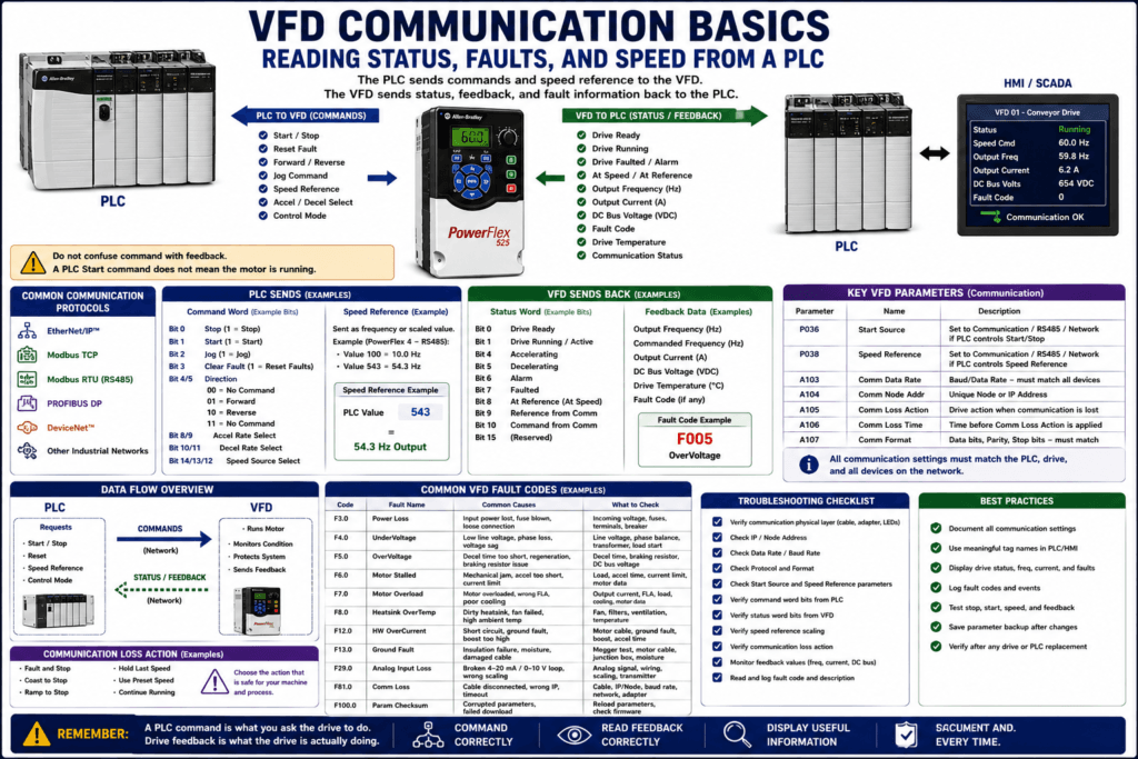
Introduction
In modern industrial automation, a Variable Frequency Drive is often more than a stand-alone motor controller. Many VFDs communicate directly with a PLC, HMI, or SCADA system.
Instead of using only hardwired signals, the PLC can exchange data with the VFD through a communication network.
This allows the control system to:
Start and stop the drive
Send a speed reference
Read drive status
Read output frequency
Read motor current
Read fault codes
Read alarm status
Monitor communication health
Reset faults
Display useful information on the HMI
The examples in this post may reference Allen-Bradley PowerFlex drives, RS485/DSI, and Modbus-style addressing, but the same concepts apply to many industrial VFDs using EtherNet/IP, Modbus TCP, Modbus RTU, PROFIBUS, PROFINET, DeviceNet, or other industrial networks.
PowerFlex documentation shows that drives can support communication modules such as DSI, DeviceNet, EtherNet/IP, PROFIBUS, embedded Modbus RTU, RS485, and PC programming through software tools.
1. Why Communicate with a VFD from a PLC?
A PLC can control a VFD with hardwired I/O, but communication gives much more information.
With hardwired control, the PLC may only know:
Run command ON
Fault contact ON
Maybe At Speed contact ON
With communication, the PLC may read:
Drive Ready
Drive Running
Drive Faulted
At Reference
Output Frequency
Commanded Frequency
Output Current
DC Bus Voltage
Fault Code
Drive Temperature
Communication Status
Control Source
Digital Input Status
This gives better troubleshooting, better HMI screens, better alarms, and better process visibility.
2. Hardwired Control vs Network Control
There are two common ways a PLC interacts with a VFD.
Hardwired Control
The PLC uses physical I/O.
Example:
PLC Digital Output → VFD Start Input
PLC Analog Output  → VFD Speed Reference
VFD Relay Output   → PLC Fault Input
VFD Analog Output  → PLC Speed or Current Feedback
Network Control
The PLC exchanges data over communication.
Example:
PLC → Command Word → VFD
PLC → Speed Reference → VFD
VFD → Status Word → PLC
VFD → Feedback Data → PLC
VFD → Fault Code → PLC
In a networked system, fewer wires may be needed, but the PLC logic and configuration become more important.
3. The Basic Communication Concept
A VFD communication system usually has two main data directions:
PLC to VFD = Commands
VFD to PLC = Status / Feedback
PLC to VFD
The PLC may send:
Start command
Stop command
Jog command
Forward / reverse command
Fault reset command
Speed reference
Accel/decel selection
Control mode selection
VFD to PLC
The drive may send back:
Ready status
Running status
Faulted status
Alarm status
At speed / at reference
Output frequency
Output current
DC bus voltage
Fault code
Communication status
Drive temperature
Simple flow:
PLC Command + Speed Reference → VFD → Motor

VFD Status + Feedback + Fault Code → PLC → HMI / Alarm Logic
4. Command Word and Status Word
Many networked drives use a command word and a status word.
Command Word
The command word is usually a group of bits sent from the PLC to the drive.
Each bit has a meaning.
Example:
Bit 0 = Stop
Bit 1 = Start
Bit 2 = Jog
Bit 3 = Clear Fault
Bit 4/5 = Direction command
Bit 8/9 = Accel profile selection
Bit 10/11 = Decel profile selection
PowerFlex 4 RS485/DSI documentation shows that the drive can be controlled by writing to a Logic Command register. It lists bits for Stop, Start, Jog, Clear Faults, Forward/Reverse command, acceleration rate selection, deceleration rate selection, and frequency source selection.
Status Word
The status word is usually a group of bits sent from the drive to the PLC.
Example:
Bit 0 = Ready
Bit 1 = Running / Active
Bit 4 = Accelerating
Bit 5 = Decelerating
Bit 6 = Alarm
Bit 7 = Faulted
Bit 8 = At Reference
Bit 9 = Reference Controlled by Communication
Bit 10 = Operation Command Controlled by Communication
PowerFlex 4 documentation shows that Logic Status can be read from the drive and includes bits for Ready, Active/Running, commanded direction, actual rotation direction, accelerating, decelerating, alarm, faulted, at reference, reference controlled by communication, and operation command controlled by communication.
5. Speed Reference from the PLC
The PLC can send a speed command to the VFD.
Depending on the system, speed reference may be sent as:
Frequency command
Percent speed command
RPM command
Engineering unit command
Integer value
Real value
Scaled network reference
For many VFDs, the speed reference eventually becomes a frequency command.
Example:
30.0 Hz
45.0 Hz
60.0 Hz
In the PowerFlex 4 RS485/DSI example, the speed reference can be written to a network register, and the decimal point is fixed. A value of 100 equals 10.0 Hz, while 543 equals 54.3 Hz.
Technician Note
Always understand scaling.
A PLC value of 600 may mean:
60.0 Hz
60.0%
600 RPM
600 engineering units
Do not assume. Check the drive manual, PLC logic, and HMI scaling.
6. Speed Feedback to the PLC
The VFD can send actual output frequency back to the PLC.
This is different from the speed command.
Speed Reference = what the PLC asks for
Output Frequency = what the drive is actually outputting
Example:
PLC Speed Reference = 60.0 Hz
Drive Output Frequency = 42.5 Hz
This may indicate the drive is still accelerating, current limiting, faulted, disabled, or not following the reference.
PowerFlex 4 documentation shows that output frequency feedback can be read through communication, and the feedback value uses the same fixed decimal format. For example, 123 equals 12.3 Hz, and 300 equals 30.0 Hz.
7. Fault Codes from the VFD
One major advantage of communication is reading the actual fault code in the PLC.
Instead of only showing:
VFD FaultedThe HMI can show:
VFD Faulted - F005 OverVoltageor:
VFD Faulted - F081 Communication LossPowerFlex 4 documentation shows that drive error codes can be read through the network, including codes such as Power Loss, Undervoltage, Overvoltage, Motor Stalled, Motor Overload, Heatsink Overtemperature, Hardware Overcurrent, Ground Fault, Analog Input Loss, Communication Loss, and Parameter Checksum Error.
Why Fault Codes Matter
A single “Faulted” bit is useful, but it is not enough for good troubleshooting.
Better HMI information:
Faulted = TRUE
Fault Code = 5
Fault Text = OverVoltage
Suggested Check = Decel time, regeneration, braking resistor, incoming voltage
This helps operators and technicians react faster.
8. Important Communication Parameters
For a VFD to communicate correctly, several parameters must match the PLC or network.
Common communication parameters include:
Protocol
Node address
IP address
Data rate
Baud rate
Communication format
Communication timeout
Communication loss action
Start source
Speed reference source
PowerFlex 4 communication setup includes parameters such as Comm Data Rate, Comm Node Address, Comm Loss Action, Comm Loss Time, and Comm Format. The documentation also states that Start Source must be set to RS485/DSI if start commands come from the network, and Speed Reference must be set to RS485/DSI if speed reference comes from the network.
9. Start Source and Speed Reference Still Matter
Even if the PLC is connected to the drive, the VFD may ignore the PLC if the parameters are not configured correctly.
The key question is:
Is the drive configured to accept commands from communication?For a PowerFlex-style example:
P036 [Start Source] = Communication / RS485 / DSI / Network
P038 [Speed Reference] = Communication / RS485 / DSI / Network
PowerFlex documentation explains that in Auto mode, the start command is defined by P036 [Start Source], and the speed reference is defined by P038 [Speed Reference].
Common Problem
The PLC is sending a Start command over the network, but the drive does not start.
Possible reason:
Start Source is still set to Keypad or Terminal Block.The PLC is sending speed over the network, but speed does not change.
Possible reason:
Speed Reference is still set to Keypad or Analog Input.10. Communication Loss Action
A VFD should have a defined response when communication is lost.
Common options may include:
Fault and stop
Coast to stop
Ramp to stop
Hold last speed
Use preset speed
Continue running
Stop after timeout
This is very important.
If communication fails, what should the motor do?
A pump, fan, conveyor, mixer, or critical process may require different behavior.
PowerFlex communication parameters include Comm Loss Action and Comm Loss Time, which define what the drive does after communication is lost and how long the drive waits before applying that action.
Technician Warning
Do not leave communication loss behavior unknown.
Ask:
[ ] If the PLC loses communication, should the drive stop?
[ ] Should it coast or ramp?
[ ] Should it fault?
[ ] Should it keep running?
[ ] Is that safe for this machine?
[ ] Does the HMI clearly show communication loss?
11. What Should the PLC Read from the VFD?
A good PLC program should read enough information to troubleshoot the drive clearly.
Recommended PLC feedback tags:
VFD_CommOK
VFD_Ready
VFD_Running
VFD_Faulted
VFD_Alarm
VFD_AtSpeed
VFD_AtReference
VFD_Accelerating
VFD_Decelerating
VFD_Forward
VFD_Reverse
VFD_OutputFreq
VFD_CommandedFreq
VFD_OutputCurrent
VFD_DCBusVoltage
VFD_FaultCode
VFD_DriveTemp
Not every system needs every tag, but the more critical the application, the more useful this feedback becomes.
12. What Should the PLC Send to the VFD?
Recommended command tags:
VFD_Start_Cmd
VFD_Stop_Cmd
VFD_Reset_Cmd
VFD_Jog_Cmd
VFD_Forward_Cmd
VFD_Reverse_Cmd
VFD_SpeedRef
VFD_AccelRate2_Enable
VFD_DecelRate2_Enable
VFD_Enable_Cmd
The exact tags depend on the drive, communication protocol, PLC platform, and machine requirements.
13. Good PLC Logic Structure
A professional PLC structure separates request, permissive, command, and feedback.
Example:
Operator_Start_Request
        ↓
Safety_Permissive_OK
        ↓
Process_Permissive_OK
        ↓
VFD_Start_Cmd
        ↓
VFD_Running_FB
        ↓
HMI Motor Running
This avoids directly mapping an HMI button to a VFD command without logic.
Better structure:
Request → Permissives → Command → VFD → Feedback → HMI / Alarm Logic14. Example PLC Tags for a Networked VFD
Command Tags
VFD_01_Start_Cmd
VFD_01_Stop_Cmd
VFD_01_Reset_Cmd
VFD_01_SpeedRef_Hz
VFD_01_Forward_Cmd
VFD_01_Reverse_Cmd
Status Tags
VFD_01_CommOK
VFD_01_Ready
VFD_01_Running
VFD_01_Faulted
VFD_01_Alarm
VFD_01_AtReference
VFD_01_Accelerating
VFD_01_Decelerating
Feedback Tags
VFD_01_OutputFreq_Hz
VFD_01_OutputCurrent_A
VFD_01_DCBusVoltage_V
VFD_01_FaultCode
VFD_01_DriveTemp_C
HMI Tags
HMI_VFD_01_StatusText
HMI_VFD_01_FaultText
HMI_VFD_01_SpeedCommand
HMI_VFD_01_OutputFrequency
HMI_VFD_01_OutputCurrent
15. Command vs Feedback
This is one of the most important automation concepts.
Command = What the PLC requests
Feedback = What the drive actually reports
Example:
VFD_Start_Cmd = ON
VFD_Running_FB = OFF
VFD_Faulted = ON
Fault Code = 7
Interpretation:
The PLC is asking the VFD to run, but the drive is faulted on Motor Overload.Another example:
VFD_SpeedRef = 60.0 Hz
VFD_OutputFreq = 0.0 Hz
VFD_Ready = FALSE
Interpretation:
The speed command exists, but the drive is not ready to run.16. HMI Display Recommendations
A good HMI should not only show “Fault.”
It should show useful drive information.
Recommended HMI display:
Drive Status: Ready / Running / Faulted / Local / Communication Loss
Speed Command: 45.0 Hz
Output Frequency: 44.8 Hz
Output Current: 6.2 A
DC Bus Voltage: 650 VDC
Fault Code: F005
Fault Description: OverVoltage
Communication Status: Healthy / Lost
Mode: Local / Remote / Auto / Hand
This helps the operator and technician understand what is happening without opening the drive cabinet.
17. Communication Troubleshooting
When the PLC is not communicating with the VFD, check:
[ ] Drive powered up
[ ] Correct communication adapter
[ ] Correct cable
[ ] Correct IP address or node address
[ ] Correct baud/data rate
[ ] Correct protocol
[ ] Correct communication format
[ ] Termination resistors, if required
[ ] Network switch port
[ ] PLC scanner configuration
[ ] Drive added correctly to PLC project
[ ] Drive communication status
[ ] Communication loss action
For RS485-style networks, PowerFlex documentation notes that termination resistors need to be applied at each end of the network cable and that repeaters may be needed for long cable runs or networks with more than 32 nodes.
18. Common Communication Problems
Problem: PLC Cannot See the Drive
Possible causes:
Wrong IP or node address
Wrong data rate
Bad cable
Bad adapter
Wrong protocol
No termination resistor
PLC scanner not configured
Drive not powered
Network switch issue
Problem: Drive Communicates but Does Not Start
Possible causes:
Start Source not set to communication
Stop input missing
Drive not ready
Drive faulted
Run permissive missing
PLC command word bits wrong
Drive in local mode
Problem: Speed Reference Does Not Work
Possible causes:
Speed Reference not set to communication
Scaling wrong
PLC value not being written
Reference source overridden
Drive in local/manual mode
Minimum/maximum frequency limiting speed
Problem: HMI Shows Wrong Status
Possible causes:
Wrong status bit mapping
Wrong data type
Wrong scaling
Old tag still used
Drive parameter changed
PLC logic using command instead of feedback
19. Reading Fault Code vs Fault Bit
A fault bit tells you:
The drive is faulted.A fault code tells you:
Why the drive is faulted.Use both.
Example PLC logic:
IF VFD_Faulted THEN
    Display VFD_FaultCode
    Trigger Alarm
    Disable Run Command
END_IF
Better HMI message:
VFD Faulted: F005 OverVoltage
Check decel time, regeneration, braking resistor, and line voltage.
20. Safety and Communication Control
A PLC communication command is not the same as a safety-rated stop.
Do not rely only on a network stop command for personnel safety unless the system is specifically designed and rated for that purpose.
Important distinction:
Normal Stop Command = process control
Safety Stop / STO / Safety Relay = safety function
The VFD installation training material warns that VFDs are intended to be commanded by control input signals, and if output isolation devices are used for emergency stop situations, auxiliary contacts should disable the drive run commands. It also reminds that I/O common terminals are not safety grounds.
21. Technician Checklist: VFD Communication Basics
Use this checklist when working with a PLC-controlled VFD:
[ ] Identify the communication protocol.
[ ] Verify drive communication adapter.
[ ] Verify IP address or node address.
[ ] Verify data rate / baud rate.
[ ] Verify communication format.
[ ] Verify PLC scanner or message configuration.
[ ] Verify Start Source is set to communication if PLC controls start.
[ ] Verify Speed Reference is set to communication if PLC controls speed.
[ ] Verify command word mapping.
[ ] Verify status word mapping.
[ ] Verify speed reference scaling.
[ ] Verify output frequency feedback scaling.
[ ] Verify fault code reading.
[ ] Verify communication loss action.
[ ] Verify HMI displays real feedback, not only commands.
[ ] Test stop/start behavior safely.
22. Common Mistakes Technicians Should Avoid
[ ] Confusing command bits with feedback bits
[ ] Assuming PLC Start command means the drive is running
[ ] Forgetting to set Start Source to communication
[ ] Forgetting to set Speed Reference to communication
[ ] Scaling speed reference incorrectly
[ ] Not reading the actual fault code
[ ] Ignoring communication loss action
[ ] Not checking node/IP address after replacement
[ ] Using HMI command as “running” indication
[ ] Not verifying local/remote mode
[ ] Not documenting communication settings
[ ] Treating network stop as a safety-rated stop
Simple Technician Explanation
A simple way to explain VFD communication is:
The PLC sends commands and speed reference to the VFD.
The VFD sends status, feedback, and fault information back to the PLC.
Or even shorter:
PLC commands the drive.
Drive feedback tells the truth.
Final Thoughts
VFD communication gives the PLC and HMI much better visibility into the drive.
Instead of only knowing that a motor is commanded to run, the PLC can know:
Is the drive ready?
Is it actually running?
Is it at speed?
What frequency is it outputting?
How much current is it drawing?
Is it faulted?
What is the fault code?
Is communication healthy?
A good technician does not only ask:
Is the PLC sending Start?A good technician also asks:
Is the drive configured to accept network control?
Is the command word correct?
Is the status word being read correctly?
Is the speed reference scaled correctly?
Is the drive feedback confirming operation?
The best communication mindset is:
Command clearly.
Read feedback correctly.
Display useful information.
Handle communication loss safely.
Document the settings.
That is what makes VFD communication valuable in real industrial automation.