17. VFDs for Fans and Pumps: PID, Pressure, Flow, and Energy Savings (17 of 19)
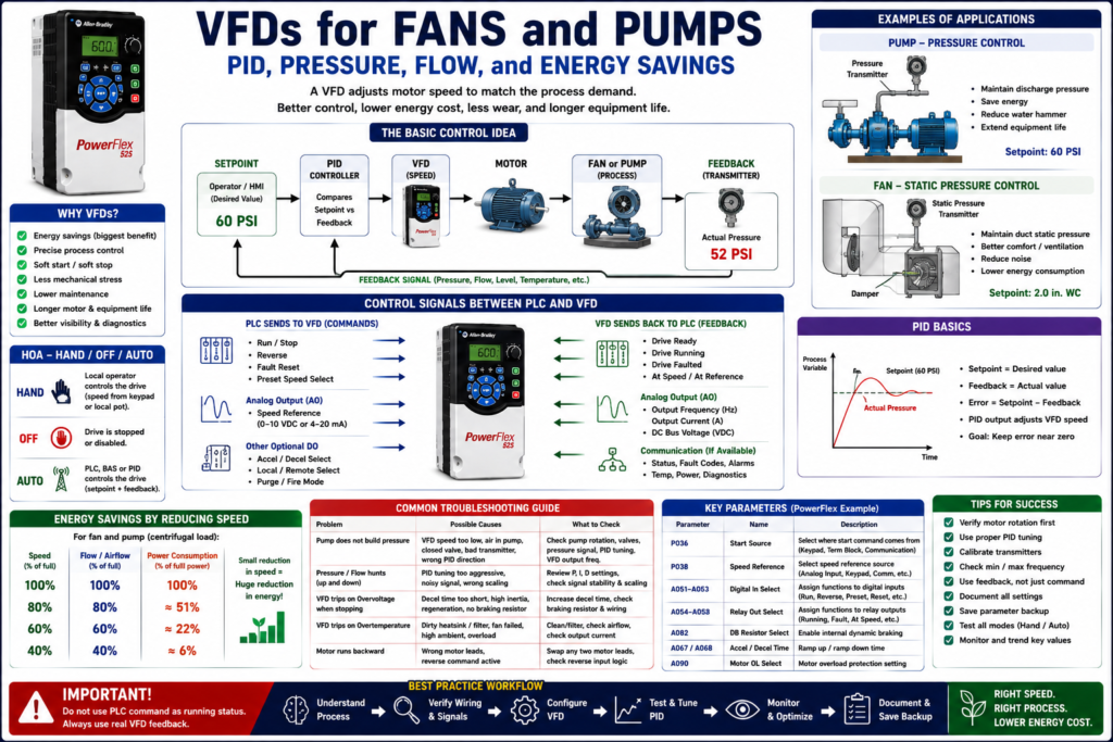
Introduction
Fans and pumps are some of the most common applications for Variable Frequency Drives in industrial automation, utilities, HVAC, water systems, process systems, and manufacturing plants.
A VFD allows a fan or pump motor to run only as fast as the process requires. Instead of running the motor at full speed all the time and controlling the process with dampers, valves, bypass lines, or mechanical restrictions, the drive can adjust motor speed electronically.
This can improve:
Energy efficiency
Process control
Equipment life
Motor starting behavior
Mechanical stress
Pressure stability
Flow stability
Operator visibility
Troubleshooting
The examples in this post use Allen-Bradley PowerFlex drives and fan/pump applications as a practical reference, but the concepts apply to most industrial VFDs regardless of manufacturer.
The PowerFlex 400 is specifically designed for fan and pump applications and includes features such as Hand-Off-Auto, fire/life safety integration, PID control, damper control, analog I/O, relay outputs, and communication options.
1. Why Fans and Pumps Are Good VFD Applications
Fans and centrifugal pumps are usually excellent VFD applications because their process output changes with speed.
For fans:
Fan speed changes airflow.
Airflow affects pressure, ventilation, cooling, exhaust, or process air.
For pumps:
Pump speed changes flow and pressure.
Flow and pressure affect water, product, chemical, cooling, or process movement.
Instead of using a fixed-speed motor and restricting flow mechanically, the VFD adjusts motor speed to match demand.
The VFD lab material also notes that drives can be used with PID controls to reduce energy cost and wear on equipment.
2. Traditional Control vs VFD Control
Traditional Fan Control
A traditional fixed-speed fan system may use:
Across-the-line starter
Full-speed motor
Dampers
Louvers
Bypass air
Manual balancing
The fan may run at 100% speed even when the process only needs 50% airflow.
VFD Fan Control
A VFD fan system may use:
VFD
Pressure transmitter
Airflow sensor
PLC or internal PID
Speed reference
Feedback signal
HMI monitoring
The drive reduces fan speed when the system demand is lower.
Traditional Pump Control
A traditional pump system may use:
Full-speed motor
Control valve
Bypass line
Pressure relief
Manual throttling
The pump may produce more flow/pressure than needed, and the system wastes energy by restricting it.
VFD Pump Control
A VFD pump system may use:
VFD
Pressure transmitter
Flow meter
Level transmitter
PLC PID or drive PID
Speed reference
Fault feedback
The VFD adjusts pump speed to maintain the required pressure, flow, or level.
3. The Basic Control Idea
Most fan and pump VFD systems follow this idea:
Process Setpoint → Controller → VFD Speed → Motor → Fan/Pump → Process FeedbackExample for pressure:
Pressure Setpoint = 60 PSI
Actual Pressure = 52 PSI
Controller increases VFD speed
Pump speeds up
Pressure rises toward 60 PSI
Example for airflow/static pressure:
Static Pressure Setpoint = 2.0 in. WC
Actual Pressure = 1.5 in. WC
Controller increases fan speed
Airflow increases
Static pressure rises toward setpoint
PowerFlex 400 documentation explains that its built-in PID loop maintains a process variable such as pressure or flow at a desired setpoint. The PID subtracts feedback from the reference, creates an error value, and outputs a frequency to reduce the error toward zero.
4. What Is PID in a VFD Application?
PID stands for:
Proportional
Integral
Derivative
In simple field language:
PID compares what you want vs what you actually have,
then adjusts the VFD speed to reduce the difference.
PID Terms
| Term | Meaning |
|---|---|
| Setpoint | Desired process value |
| Feedback | Actual measured process value |
| Error | Difference between setpoint and feedback |
| Output | Speed command sent to the VFD |
| Process Variable | Pressure, flow, level, temperature, etc. |
Example:
Setpoint = 60 PSI
Feedback = 55 PSI
Error = 5 PSI
PID Output = Increase VFD speed
5. Internal Drive PID vs PLC PID
A PID loop can be located in different places.
Internal VFD PID
The drive itself performs PID control.
Typical signals:
Pressure transmitter → VFD analog input
PID setpoint → VFD parameter, keypad, analog input, or communication
VFD PID output → motor speed
Best for:
Simple pump control
Simple fan static pressure control
Standalone systems
Systems without PLC PID
HVAC-style control
PLC PID
The PLC performs PID control and sends a speed reference to the VFD.
Typical signals:
Pressure transmitter → PLC analog input
PLC PID calculates speed command
PLC analog/network output → VFD speed reference
VFD controls motor
Best for:
More complex automation
Multiple pumps or fans
Sequencing
Lead/lag control
Recipe-based control
Advanced alarms
Centralized HMI control
Technician Note
Do not run two PID loops fighting each other.
Bad setup:
PLC PID controls speed reference
AND
VFD internal PID also controls speed
This can cause unstable speed, hunting, oscillation, and poor process control.
Good rule:
One PID loop should be in control.
The other device should act as speed command follower.
6. Pressure Control Example: Pump System
A common VFD pump application is pressure control.
System Components
Pump motor
VFD
Pressure transmitter
PLC or VFD PID
HMI setpoint
Run permissives
Fault feedback
Control Sequence
1. Operator enters pressure setpoint.
2. Pump receives run command.
3. Pressure transmitter measures actual pressure.
4. PID compares setpoint and feedback.
5. PID increases or decreases VFD speed.
6. Pump output pressure stabilizes near setpoint.
Example
Setpoint = 80 PSI
Actual pressure = 70 PSI
VFD speed increases

Setpoint = 80 PSI
Actual pressure = 85 PSI
VFD speed decreases
7. Flow Control Example: Pump or Process Line
Another common application is flow control.
System Components
Pump
VFD
Flow meter
PLC PID or drive PID
Flow setpoint
Control valve, if required
Example
Flow Setpoint = 100 GPM
Actual Flow = 85 GPM
VFD increases pump speed
Flow control is common in:
Chemical dosing
Water transfer
CIP systems
Process filling
Cooling loops
Product transfer
8. Static Pressure Control Example: Supply Fan
A supply fan may be controlled by duct static pressure.
System Components
Supply fan motor
VFD
Duct static pressure transmitter
PID controller
Dampers or VAV boxes
HMI setpoint
Control Concept
If duct pressure is low → increase fan speed
If duct pressure is high → decrease fan speed
PowerFlex 400 documentation includes an application diagram where PID feedback comes from a pressure transducer signal, the PID reference is the desired static pressure, and the fan system uses supply/return fan airflow and dampers.
9. Damper Control with a VFD
In some fan applications, the VFD can coordinate with dampers.
The PowerFlex 400 documentation explains that damper control logic can be embedded in the drive. A system Run command can be wired to the drive, relay outputs can energize the damper to open or close, and a damper limit switch can be wired back to confirm the damper is in the proper position before the drive runs at commanded speed.
Example Sequence
1. Run command is requested.
2. VFD commands damper to open.
3. Damper open limit switch confirms position.
4. VFD allows fan to run.
5. PID controls fan speed.
This prevents the fan from running against a closed damper.
10. Hand-Off-Auto in Fan and Pump Applications
Many fan and pump systems use Hand-Off-Auto, also called HOA.
Hand Mode
Local operator controls the drive.
Speed may come from keypad/HIM or local potentiometer.
Useful for maintenance and manual testing.
Off Mode
Drive is stopped or disabled.Auto Mode
PLC, BAS, process controller, or PID loop controls the drive.PowerFlex 400 documentation describes configurable Hand-Off-Auto behavior. In Hand mode, the start command and speed reference can come from the integral keypad; in Auto mode, the start command is defined by P036 [Start Source], and speed reference is defined by P038 [Speed Reference].
11. Purge, Fire, and Freeze Inputs
Fan systems may connect to fire or life-safety systems.
PowerFlex 400 documentation describes a Purge input that can be wired to a fire control panel or life-safety system. When active, it can start the drive at a programmed purge speed regardless of selected start source, and it can operate whether the drive is running or stopped.
The same documentation describes Fire/Freeze Stats using a Function Loss input. If the input opens, the drive immediately coasts to stop and faults; the drive is allowed to restart only after the alarm clears and the drive fault is reset.
Technician Note
Always document these inputs clearly.
A technician troubleshooting a fan VFD must know if the system includes:
Fire alarm input
Purge override
Freeze stat
Smoke control
Damper proving switch
Building automation system command
These may override normal PLC or keypad expectations.
12. Energy Savings: Why Speed Reduction Matters
One major reason to use VFDs on fans and pumps is energy savings.
For many centrifugal fans and pumps, reducing speed can significantly reduce power demand.
Simple concept:
Less speed = less flow
Less flow = much less power required
This is why controlling speed is often better than running full speed and throttling flow mechanically.
Practical Example
Instead of:
Pump runs 100% speed
Valve throttles flow
Energy is wasted across restriction
Use:
Pump slows down
Flow matches demand
Less energy is consumed
Less mechanical stress occurs
Even without doing advanced calculations, the technician should understand the field idea:
A VFD saves energy by reducing motor speed when full output is not required.13. Variable Torque vs Constant Torque
Fans and centrifugal pumps are usually considered variable torque loads.
Variable torque loads typically require less torque at lower speeds.
Examples:
Centrifugal fans
Centrifugal pumps
Blowers
Some HVAC equipment
Constant torque loads are different.
Examples:
Conveyors
Positive displacement pumps
Mixers
Screw feeders
Extruders
A fan or centrifugal pump is often easier to control with a VFD than a heavy constant-torque load, but the application still must be verified.
14. Minimum Speed Considerations
Do not assume a fan or pump can run at any low speed.
Minimum speed may be limited by:
Motor cooling
Pump lubrication
Minimum flow
Cooling requirements
Process stability
Bearing lubrication
Fan airflow requirements
Mechanical resonance
Pressure control stability
For pumps, running too slow may cause insufficient flow or poor cooling.
For fans, running too slow may not provide enough airflow for the process.
15. Maximum Speed Considerations
Do not increase maximum frequency without checking the machine.
Overspeed may damage:
Pump impeller
Fan wheel
Bearings
Couplings
Belts
Seals
Motor
Ductwork
Piping
Increasing a VFD from 60 Hz to 70 Hz may seem simple, but it can create mechanical and process risks.
Good technician question:
Is the motor and driven equipment rated for this speed?16. Pump Troubleshooting with VFDs
Pump Does Not Build Pressure
Possible causes:
VFD speed reference too low
Pump running backward
Air in pump
Closed suction valve
Blocked suction strainer
Low tank level
Bad pressure transmitter
Incorrect PID setup
Pump mechanical issue
Pump Trips on Overload
Possible causes:
Pump jammed
Discharge blocked
High viscosity
Motor FLA set incorrectly
Bearing issue
Impeller problem
VFD current limit too low
Pressure Hunts Up and Down
Possible causes:
PID tuning too aggressive
Pressure transmitter noise
Minimum speed too high
Control valve interaction
Two PID loops fighting
Process demand changing rapidly
17. Fan Troubleshooting with VFDs
Fan Does Not Produce Airflow
Possible causes:
Fan running backward
Damper closed
Belt broken or slipping
VFD speed reference too low
Static pressure sensor issue
Duct blockage
Wrong PID direction
Fan Trips on Overvoltage When Stopping
Possible causes:
High inertia fan
Decel time too short
Regeneration into DC bus
No braking resistor
Stop mode not suitable
Fan Trips on Overtemperature
Possible causes:
Dirty drive heatsink
Panel fan failed
Cabinet filter clogged
High ambient temperature
Drive undersized
Motor overloaded
18. Good PLC/HMI Tags for Fan and Pump VFDs
Command Tags
Pump_Run_Cmd
Fan_Run_Cmd
VFD_Reset_Cmd
VFD_SpeedRef_Hz
PID_Setpoint
HOA_Auto_Mode
Feedback Tags
VFD_Ready
VFD_Running
VFD_Faulted
VFD_AtSpeed
VFD_OutputFreq
VFD_OutputCurrent
Process Feedback Tags
Pressure_PV
Flow_PV
Level_PV
StaticPressure_PV
PID_Output
Alarm Tags
Pressure_Low_Alarm
Pressure_High_Alarm
Flow_Low_Alarm
VFD_Fault_Alarm
Feedback_Timeout
Damper_Not_Open_Fault
19. Recommended HMI Display
A good HMI screen for a fan or pump VFD should show:
Mode: Hand / Off / Auto
Run Command
Running Feedback
Faulted Status
Speed Setpoint
Output Frequency
Output Current
Process Setpoint
Process Feedback
PID Output
Communication Status
Fault Code
Damper Status, if fan system
Do not show only command status.
Better:
Commanded to Run: Yes
Actually Running: Yes
Output Frequency: 42.5 Hz
Pressure Feedback: 58 PSI
Setpoint: 60 PSI
PID Output: 71%
20. Common Mistakes Technicians Should Avoid
[ ] Assuming the VFD is bad when pressure is low
[ ] Not checking motor rotation
[ ] Forgetting damper position or valve position
[ ] Running two PID loops at the same time
[ ] Setting minimum speed too low
[ ] Setting maximum speed too high
[ ] Ignoring pressure/flow transmitter scaling
[ ] Ignoring analog signal noise
[ ] Not checking HOA mode
[ ] Forgetting fire/purge/freeze inputs
[ ] Making PID changes without recording original values
[ ] Using command status instead of real feedback
21. Technician Checklist: VFDs for Fans and Pumps
[ ] Identify the load: fan, blower, centrifugal pump, or other.
[ ] Verify motor nameplate data.
[ ] Verify fan/pump rotation.
[ ] Verify Start Source.
[ ] Verify Speed Reference.
[ ] Verify HOA mode.
[ ] Verify process transmitter signal.
[ ] Verify analog scaling.
[ ] Verify PID setpoint.
[ ] Verify PID feedback.
[ ] Verify PID output.
[ ] Verify minimum and maximum frequency.
[ ] Verify accel/decel time.
[ ] Verify stop mode.
[ ] Check damper/valve position.
[ ] Check fault history.
[ ] Check VFD output current.
[ ] Check feedback to PLC/HMI.
[ ] Save parameter backup before changes.
Simple Technician Explanation
A simple way to explain fan and pump VFD control is:
A sensor measures the process.
The controller compares the measurement to the setpoint.
The VFD changes motor speed.
The fan or pump output changes.
The process moves closer to the setpoint.
Or even shorter:
Setpoint + Feedback + PID = VFD speed control.Final Thoughts
Fans and pumps are some of the best applications for VFDs because their speed can be adjusted to match process demand.
A good technician does not only ask:
Is the VFD running?A good technician asks:
Is the process feedback correct?
Is the setpoint correct?
Is PID in the PLC or inside the drive?
Is the drive following the speed reference?
Is the fan or pump rotating in the correct direction?
Are valves or dampers in the correct position?
Is the HMI showing command or real feedback?
The best troubleshooting mindset for fan and pump VFDs is:
Verify the drive.
Verify the motor.
Verify the process feedback.
Verify the mechanical path.
Verify the control loop.
That is how VFD fan and pump systems become easier to understand, tune, and troubleshoot.