16. Analog Signals: 4–20 mA, 0–10 VDC, and PLC Scaling
In industrial automation, not every signal is simply ON or OFF.
Some devices need to send a real measurement to the PLC.
Examples:
Pressure = 72.5 PSI
Tank Level = 63%
Temperature = 180°F
Flow = 125 GPM
Weight = 250 lbs
These values are usually sent to the PLC using analog signals.
The most common analog signals are:
4–20 mA
0–10 VDC
1–5 VDC
RTD
Thermocouple
Millivolt signals
For automation technicians, understanding analog signals is critical because many process problems are not simple input/output problems.
They may be caused by:
Wrong scaling
Missing loop power
Bad transmitter
Broken wire
Wrong analog card configuration
Noisy signal
Grounding issue
Incorrect engineering units
Bad HMI tag
Wrong instrument range
The goal is to understand how a real process value becomes a number in the PLC and then becomes a meaningful value on the HMI.
1. Discrete Signal vs Analog Signal
Discrete Signal
A discrete signal has only two states.
ON or OFF
TRUE or FALSE
1 or 0
Examples:
Photoeye ON/OFF
Limit switch open/closed
Pressure switch made/not made
Proximity sensor target/no target
Analog Signal
An analog signal represents a variable measurement.
Low value → High value
Minimum → Maximum
0% → 100%
Examples:
4–20 mA = 0–100 PSI
0–10 VDC = 0–500 RPM
4–20 mA = 0–100% tank level
RTD = temperature measurement
Simple difference:
Discrete = condition
Analog = measurement
2. What Is a 4–20 mA Signal?
A 4–20 mA signal is a current signal used to represent a process measurement.
Example:
4 mA  = minimum value
20 mA = maximum value
For a pressure transmitter ranged from 0 to 100 PSI:
4 mA  = 0 PSI
20 mA = 100 PSI
12 mA = 50 PSI
This allows the transmitter to send a variable value to the PLC analog input card.
3. Why 4 mA Instead of 0 mA?
One major advantage of 4–20 mA is the live zero.
4 mA = valid zero measurement
0 mA = possible broken wire or failed loop
Example:
If a pressure transmitter is ranged 0–100 PSI:
4 mA = 0 PSIThat means zero pressure is still a valid signal.
But if the PLC reads:
0 mAThat may indicate:
Broken wire
No loop power
Failed transmitter
Open circuit
Disconnected analog input
Bad fuse
This is why 4–20 mA is very popular in industrial instrumentation.
4. What Is a 0–10 VDC Signal?
A 0–10 VDC signal is a voltage signal used to represent a measurement.
Example:
0 VDC  = minimum value
10 VDC = maximum value
For a speed reference:
0 VDC  = 0 RPM
10 VDC = 1800 RPM
5 VDC  = 900 RPM
0–10 VDC is common for:
Speed references
Position sensors
Some pressure sensors
Some level sensors
Actuator commands
VFD analog inputs
5. 4–20 mA vs 0–10 VDC
| Feature | 4–20 mA | 0–10 VDC |
|---|---|---|
| Signal type | Current | Voltage |
| Common use | Process instrumentation | Speed/reference signals, sensors |
| Noise resistance | Better | More sensitive |
| Long cable runs | Better | Less ideal |
| Broken wire detection | Easier because 0 mA is abnormal | Harder because 0 V can be valid |
| Typical devices | Pressure, flow, level transmitters | VFD references, position sensors |
| Wiring sensitivity | Less affected by voltage drop | More affected by voltage drop |
In many industrial process systems, 4–20 mA is preferred because it is more robust over distance and more noise-resistant.
6. What Is a PLC Analog Input?
A PLC analog input module receives a variable electrical signal.
Examples:
4–20 mA
0–10 VDC
1–5 VDC
RTD
Thermocouple
The analog input converts that signal into a digital number inside the PLC.
This digital number is often called:
Raw counts
Raw value
Analog raw input
Digital value
Example:
12 mA signal enters the analog input card.
PLC converts it to a raw count.
PLC scaling logic converts raw count to PSI.
7. What Are Raw Counts?
Raw counts are the digital value created by the analog input module.
The PLC does not automatically know that the signal means PSI, gallons, degrees, or percent.
It only sees a number.
Example:
Raw Value = 16384That number must be scaled into engineering units.
Depending on the PLC and analog module, raw counts may use different ranges.
Examples:
0–32767
0–27648
4000–20000
6242–31208
-32768 to 32767
Always check the analog module manual or configuration.
8. What Is Scaling?
Scaling converts the raw analog input value into real engineering units.
Simple definition:
Scaling = converting raw PLC counts into real-world values.Example:
Raw Counts → Scaling → PSIFor a pressure transmitter:
4–20 mA = 0–100 PSIThe PLC must convert the input signal into:
Pressure_PSISo the HMI can display:
Tank Pressure = 72.5 PSI9. Engineering Units
Engineering units are the real-world units used by operators, technicians, and engineers.
Examples:
PSI
°F
°C
GPM
LPM
%
lbs
kg
inches
feet
RPM
pH
conductivity
Raw values are useful for the PLC.
Engineering units are useful for humans.
Example:
Raw value = 21450is not as helpful as:
Tank Level = 67.3%10. Basic Scaling Example: 4–20 mA to PSI
Assume:
Transmitter range: 0–100 PSI
Signal range: 4–20 mA
Values:
4 mA  = 0 PSI
12 mA = 50 PSI
20 mA = 100 PSI
This is a linear relationship.
So if the PLC sees the middle of the signal range, the process value is the middle of the engineering range.
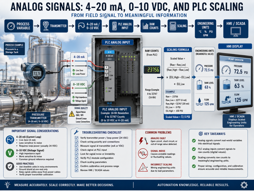
11. Scaling Formula Concept
The general scaling concept is:
Scaled Value =
((Raw Value - Raw Low) / (Raw High - Raw Low))
× (Engineering High - Engineering Low)
+ Engineering Low
Example concept:
Raw Low = value at 4 mA
Raw High = value at 20 mA
Engineering Low = 0 PSI
Engineering High = 100 PSI
In many PLCs, you may use a scaling instruction instead of manually writing the formula.
Examples:
SCP in RSLogix 500
SCL or CPT style logic
SCALE / NORM logic depending on platform
AOI scaling block in Studio 5000
12. RSLogix 500 Example: SCP Instruction
In RSLogix 500, the SCP instruction is commonly used for scaling.
Example:
Input Min  = Raw value at 4 mA
Input Max  = Raw value at 20 mA
Scaled Min = 0 PSI
Scaled Max = 100 PSI
Output     = Pressure_PSI
Concept:
Analog Raw Input → SCP → Engineering UnitsExample:
I:1.0 Raw Analog Input
SCP Instruction
N7:0 Pressure_PSI
The exact raw min and max depend on the analog card.
13. Studio 5000 Example: Scaling
In Studio 5000, analog scaling depends on the module configuration and programming style.
Some analog modules can be configured to provide engineering units directly.
Other systems use logic to scale raw values.
Common methods include:
CPT instruction
SCL instruction, depending on platform
AOI scaling block
Module configuration scaling
Structured Text formula
Function Block scaling
Example tag structure:
AI_TankPressure_Raw
AI_TankPressure_PSI
AI_TankPressure_Fault
AI_TankPressure_HighAlarm
AI_TankPressure_LowAlarm
Good tag names make troubleshooting much easier.
14. Analog Signal Fault Detection
Analog signals should be monitored for bad values.
For 4–20 mA, abnormal values may indicate problems.
Examples:
Less than 3.6 mA = possible underrange or fault
Around 0 mA = open circuit or no loop power
Greater than 20.5 mA = overrange or fault
Exact limits depend on the transmitter and system design.
Common fault logic:
Analog signal below valid range = Instrument Fault
Analog signal above valid range = Instrument Fault
Example:
Pressure signal below 3.5 mA for 2 seconds
= Pressure Transmitter Fault
This helps the PLC distinguish between a real low process value and a failed signal.
15. Common Analog Problems
Analog problems can be tricky because the signal may not be completely ON or OFF.
Common issues:
Signal stuck at zero
Signal stuck at maximum
Signal noisy
Signal drifting
Signal jumping
Wrong scaling
Wrong range
Wrong units
No loop power
Reversed polarity
Broken wire
Bad shield grounding
Ground loop
Wrong analog card configuration
Bad transmitter
Bad analog input channel
The technician must separate:
Process problem
Instrument problem
Wiring problem
PLC configuration problem
Scaling problem
HMI display problem
16. Troubleshooting Example: HMI Shows 0 PSI
Problem:
HMI Pressure = 0 PSIPossible causes:
Actual pressure is zero
Transmitter has no power
4–20 mA loop is open
Wire is broken
Analog input channel is bad
PLC scaling is wrong
HMI tag is wrong
Impulse line is blocked
Transmitter failed
Troubleshooting path:
1. Check actual process condition.
2. Check transmitter display if available.
3. Check 24 VDC loop power.
4. Measure loop current.
5. Check signal at terminal block.
6. Check PLC raw analog value.
7. Check scaling logic.
8. Check HMI tag and engineering units.
17. Troubleshooting Example: Signal Is Noisy
Problem:
Tank level jumps between 40% and 75%.Possible causes:
Loose terminal
Bad shield
Ground loop
VFD noise
Cable routed with motor leads
Unstable power supply
Bad analog input card
Actual process turbulence
Foam in tank
Wrong instrument technology
Troubleshooting path:
1. Compare local transmitter display to HMI.
2. Check raw analog value in PLC.
3. Measure signal with meter or loop calibrator.
4. Inspect wiring and shield.
5. Check cable routing.
6. Check grounding and bonding.
7. Check process condition.
8. Check scaling and filtering.
18. Analog Filtering
Sometimes analog signals need filtering.
Filtering smooths a noisy signal.
Examples:
Moving average
Low-pass filter
PLC filter setting
Analog input module filter
HMI display smoothing
However, filtering should be used carefully.
Too much filtering can make the signal slow to respond.
Example:
A level signal may be safely filtered.
A fast pressure control loop may need faster response.
Do not hide a real wiring or grounding problem with excessive filtering.
19. Calibration vs Scaling
This is very important.
Calibration
Calibration verifies the instrument output matches the real process value.
Example:
Actual pressure = 50 PSI
Transmitter output = 12 mA
Calibration is about instrument accuracy.
Scaling
Scaling converts the PLC input value into engineering units.
Example:
12 mA = 50 PSIScaling is about PLC interpretation.
Simple difference:
Calibration = Is the transmitter accurate?
Scaling = Is the PLC interpreting the signal correctly?
A transmitter can be calibrated correctly but scaled incorrectly.
A PLC can be scaled correctly but the transmitter can be out of calibration.
20. Technician Checklist
When troubleshooting analog signals, verify:
Instrument type
Instrument range
Signal type
4–20 mA or 0–10 VDC
Loop power present
Wiring polarity correct
Terminal block connections tight
Shielding and grounding correct
Analog input card configuration
Raw analog value changing
Scaling raw min and raw max
Engineering low and high values
Engineering units correct
HMI tag correct
Alarm limits correct
Signal fault limits configured
Actual process condition verified
Calibration status known
Final Thoughts
Analog signals are essential in industrial automation because they allow the PLC to understand real process measurements.
Discrete inputs tell the PLC if something is ON or OFF.
Analog inputs tell the PLC how much.
Pressure
Temperature
Level
Flow
Weight
Speed
Position
A strong automation technician understands how the signal moves:
Process Variable → Transmitter → Analog Signal → PLC Analog Input → Raw Counts → Scaling → Engineering Units → HMI / SCADAWhen troubleshooting, do not guess.
Check the process.
Check the instrument.
Check loop power.
Measure the signal.
Check raw counts.
Verify scaling.
Confirm engineering units.
Compare the HMI with the real condition.
Analog troubleshooting is about proving whether the problem is in the process, the instrument, the wiring, the PLC, the scaling, or the display.
Understanding analog signals is a major step toward becoming a stronger automation technician.