15. Industrial Instrumentation Basics for Automation Technicians
Industrial instrumentation is one of the most important areas of automation.
Sensors tell the PLC when something is ON or OFF.
Instrumentation tells the PLC how much, how high, how hot, how heavy, how fast, or how much pressure exists in the process.
A photoeye may tell the PLC:
Box present = ON
Box missing = OFF
But a pressure transmitter tells the PLC:
Pressure = 72.5 PSIA level transmitter tells the PLC:
Tank level = 63%A flow meter tells the PLC:
Flow = 125 gallons per minuteInstrumentation is what allows automation systems to measure, control, trend, alarm, and improve industrial processes.
1. What Is Industrial Instrumentation?
Industrial instrumentation is the field of measuring and controlling process variables.
A process variable is something in the process that can be measured.
Common process variables include:
Temperature
Pressure
Level
Flow
Weight
Speed
Position
pH
Conductivity
Humidity
Density
Instrumentation devices convert real-world physical conditions into electrical signals that the PLC, HMI, or SCADA system can understand.
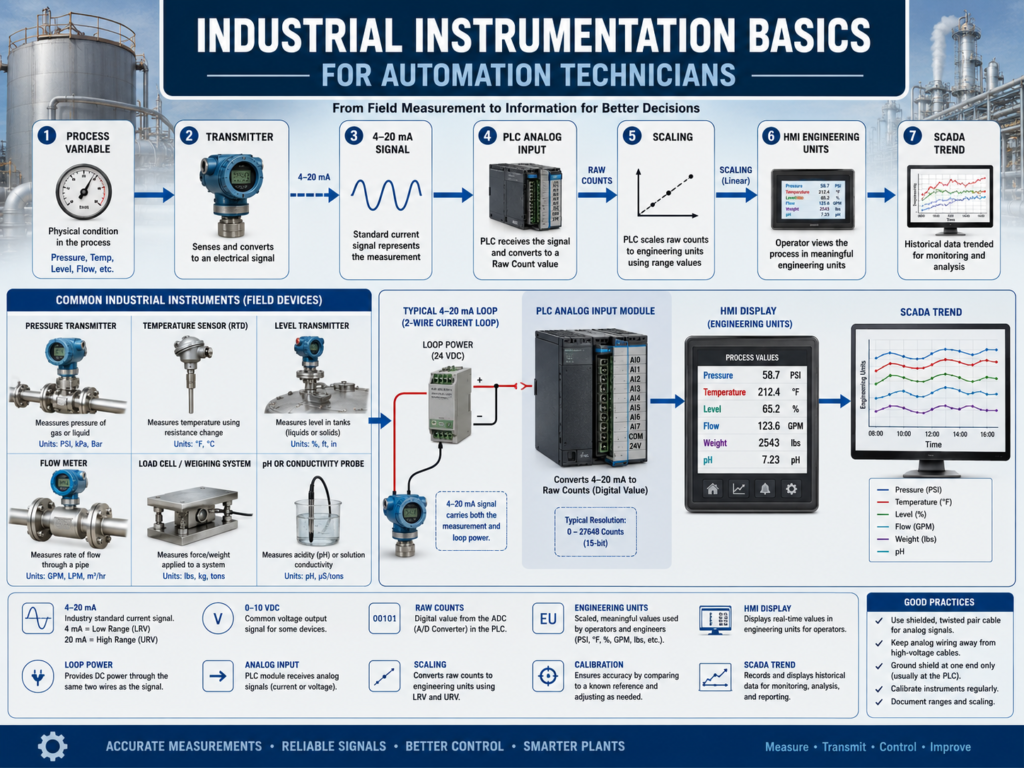
Basic concept:
Physical Process Variable
        ↓
Instrument / Transmitter
        ↓
Electrical Signal
        ↓
PLC Analog Input
        ↓
Engineering Units
        ↓
HMI / SCADA Display
Example:
Tank pressure
     ↓
Pressure transmitter
     ↓
4–20 mA signal
     ↓
PLC analog input
     ↓
0–100 PSI
     ↓
HMI display
2. Sensors vs Instruments
In automation, people sometimes use the word “sensor” for everything. But from a technical point of view, there is a useful difference.
Sensor
A sensor detects a condition.
Example:
Photoeye detects bottle present.
Limit switch detects door closed.
Proximity sensor detects metal target.
Most basic sensors are discrete:
ON or OFF
TRUE or FALSE
1 or 0
Instrument
An instrument measures a process value.
Example:
Pressure transmitter measures PSI.
Temperature transmitter measures degrees.
Flow meter measures gallons per minute.
Load cell system measures weight.
Level transmitter measures tank level.
Most instruments are analog or digital measurement devices.
Simple difference:
Sensor = detects condition
Instrument = measures value
3. Common Process Variables
Pressure
Pressure instruments measure force applied by gas or liquid inside a system.
Common applications:
Air pressure
Water pressure
Steam pressure
Hydraulic pressure
Tank pressure
Pump discharge pressure
Filter differential pressure
Common units:
PSI
bar
kPa
inH₂O
Example:
4 mA  = 0 PSI
20 mA = 100 PSI
Temperature
Temperature instruments measure heat.
Common devices:
RTD
Thermocouple
Temperature transmitter
Infrared temperature sensor
Temperature switch
Common applications:
Pasteurizers
Ovens
Heat exchangers
Tanks
Motors
Bearings
Sealing jaws
Process lines
Common units:
°F
°C
K
Level
Level instruments measure how much material is inside a tank, hopper, or vessel.
Common applications:
Tank level
Silo level
Hopper level
Chemical level
Water level
Product level
Powder level
Common technologies:
Ultrasonic
Radar
Pressure-based level
Float
Capacitive
Guided wave radar
Load cells
Level may be measured as:
Percent
Inches
Feet
Gallons
Liters
Flow
Flow instruments measure how much liquid, gas, or steam moves through a pipe.
Common applications:
Water flow
Product flow
CIP flow
Steam flow
Compressed air flow
Chemical dosing
Filling systems
Common units:
GPM
LPM
CFM
SCFM
kg/hr
lb/hr
Common flow meter types:
Magnetic flow meter
Coriolis flow meter
Turbine flow meter
Vortex flow meter
Ultrasonic flow meter
Differential pressure flow meter
Weight
Weight measurement is commonly done with load cells.
Common applications:
Filling machines
Batch tanks
Checkweighers
Hoppers
Silos
Scales
Ingredient batching
A load cell produces a very small electrical signal, usually measured in millivolts, which is then converted by a scale indicator or transmitter.
Example:
Load Cell → Junction Box → Scale Indicator → PLC4. What Is a Transmitter?
A transmitter converts a measurement into a usable signal.
Example:
Pressure sensor detects pressure.
Transmitter converts pressure into 4–20 mA.
PLC reads the 4–20 mA signal.
Simple definition:
Transmitter = Device that converts a process measurement into an electrical signal.Common transmitter signals:
4–20 mA
0–10 VDC
1–5 VDC
HART
IO-Link
EtherNet/IP
Modbus
Profibus PA
Foundation Fieldbus
A transmitter usually has:
Power terminals
Signal terminals
Process connection
Configuration parameters
Range settings
Calibration settings
Display, depending on model
5. Analog Signals
Analog signals represent a variable measurement.
Unlike discrete signals, analog signals can have many values.
Discrete example:
0 or 1
OFF or ON
Analog example:
0 PSI to 100 PSI
0% to 100% tank level
32°F to 250°F
0 to 500 GPM
Common analog signals in automation:
4–20 mA
0–10 VDC
1–5 VDC
0–5 VDC
RTD
Thermocouple
Millivolt load cell signals
6. Why 4–20 mA Is So Common
The 4–20 mA signal is one of the most common instrumentation signals.
Example:
4 mA  = Minimum value
20 mA = Maximum value
For a 0–100 PSI pressure transmitter:
4 mA  = 0 PSI
20 mA = 100 PSI
Why not 0–20 mA?
Because 4 mA provides a live zero.
That means the PLC can detect a broken wire or failed loop.
Example:
0 mA = Possible broken wire or failed transmitter
4 mA = Valid minimum reading
20 mA = Valid maximum reading
This is one reason 4–20 mA is very popular in industrial environments.
7. Scaling in the PLC
The PLC does not automatically know that 4–20 mA means 0–100 PSI.
The PLC analog input reads a raw value.
Then the program scales that raw value into engineering units.
Example:
Raw Analog Input
        ↓
Scaling Logic
        ↓
Engineering Units
Example result:
Raw signal = 12 mA
Scaled value = 50 PSI
The technician must understand:
Instrument range
PLC analog card configuration
Raw input range
Engineering unit range
Scaling instruction or formula
HMI display range
Alarm setpoints
If scaling is wrong, the instrument may be working correctly but the HMI value may be wrong.
8. Engineering Units
Engineering units are real-world units displayed to operators and technicians.
Examples:
PSI
°F
°C
GPM
LPM
%
lbs
kg
inches
feet
RPM
Good automation systems should display values in units that make sense to the process.
Example:
Bad display:
Analog_Value = 14352

Good display:
Tank Pressure = 62.4 PSI
Raw values are useful for programming.
Engineering units are useful for operators and troubleshooting.
9. Calibration vs Scaling
This is an important distinction.
Calibration
Calibration verifies or adjusts the instrument so its output matches the real process value.
Example:
Actual pressure = 50 PSI
Transmitter output should equal 12 mA
Calibration is usually done with reference equipment.
Examples:
Pressure calibrator
Temperature calibrator
Loop calibrator
Deadweight tester
Known weights
Reference thermometer
Scaling
Scaling is done in the PLC or HMI to convert the signal into engineering units.
Example:
4–20 mA = 0–100 PSISimple difference:
Calibration = instrument accuracy
Scaling = PLC interpretation
A transmitter can be calibrated correctly but scaled incorrectly in the PLC.
Or the PLC scaling can be correct while the transmitter is out of calibration.
10. Loop Power
Many instruments require 24 VDC loop power.
A common 2-wire transmitter uses the same two wires for power and signal.
Basic 2-wire loop concept:
24 VDC Supply
     ↓
Transmitter
     ↓
Analog Input
     ↓
Return to supply
The transmitter controls the loop current between 4 and 20 mA.
This current represents the process value.
Technician checks:
Is 24 VDC loop power present?
Is the loop wired in series?
Is polarity correct?
Is the analog input configured correctly?
Is the loop current correct?
11. 2-Wire, 3-Wire, and 4-Wire Instruments
2-Wire Instrument
Power and signal share the same loop.
Common for:
Pressure transmitters
Level transmitters
Temperature transmitters
3-Wire Instrument
Usually has separate power, common, and signal.
Common for:
0–10 VDC sensors
Some analog transmitters
Some position sensors
4-Wire Instrument
Has separate power and signal wiring.
Common for:
Flow meters
Analyzer systems
Powered transmitters
Devices with their own supply
Always check the wiring diagram.
Do not assume all instruments wire the same way.
12. Instrumentation and the HMI
The HMI displays instrument values to the operator.
Example HMI values:
Tank Level = 78%
Flow Rate = 125 GPM
Temperature = 180°F
Pressure = 62 PSI
Weight = 245 lbs
The HMI may also display alarms:
High Pressure Alarm
Low Level Alarm
High Temperature Fault
Flow Not Detected
Weight Out of Tolerance
Good HMI design should show:
Current value
Engineering units
Alarm limits
Setpoints
Trend
Instrument status
Fault condition
13. Instrumentation and SCADA
SCADA systems use instrumentation for:
Trends
Reports
Historical data
Batch records
Alarm history
Production analysis
Energy monitoring
Quality monitoring
Process optimization
Example:
Temperature trend over 24 hours
Flow total for production shift
Tank level history
Pressure alarm history
Batch weight record
Instrumentation turns the process into data.
That data helps operators, maintenance, quality, engineering, and management understand the process better.
14. Common Instrumentation Problems
Common problems include:
No signal
Signal stuck at 0
Signal stuck at maximum
Signal noisy
Signal drifting
Wrong scaling
Wrong range
Broken wire
Missing loop power
Wrong polarity
Bad transmitter
Plugged impulse line
Dirty probe
Bad ground/shield
Analog card fault
Configuration mismatch
A technician must determine whether the problem is:
Process problem
Instrument problem
Wiring problem
PLC input problem
Scaling problem
HMI display problem
15. Basic Instrument Troubleshooting Method
Use a logical method:
1. Understand what the instrument measures.
2. Check the process condition.
3. Check instrument power.
4. Check loop current or voltage signal.
5. Check terminal block wiring.
6. Check PLC analog input value.
7. Check scaling in the PLC.
8. Check HMI engineering units.
9. Check alarm limits.
10. Document the root cause.
For 4–20 mA signals:
Approximately 4 mA = low end
Approximately 20 mA = high end
0 mA usually indicates a loop problem
Greater than 20 mA may indicate overrange or fault, depending on transmitter configuration
16. Example: Pressure Reading Stuck at 0 PSI
Problem
HMI shows:
Pressure = 0 PSIPossible causes:
Actual pressure is zero
Transmitter has no power
4–20 mA loop open
Broken wire
Wrong analog input channel
PLC scaling issue
Transmitter failed
Isolation valve closed
Impulse line plugged
Troubleshooting path:
Check actual process pressure.
Check transmitter display, if available.
Measure loop current.
Check 24 VDC loop power.
Check terminal block.
Check PLC raw analog value.
Check scaling.
Check HMI tag.
17. Example: Level Reading Jumping
Problem
Tank level jumps from 55% to 80% randomly.
Possible causes:
Noisy signal
Bad shield grounding
Loose terminal
Unstable 24 VDC
Foam or turbulence in tank
Incorrect sensor technology
VFD noise
Ground loop
Bad analog input card
Troubleshooting path:
Check local instrument display.
Check analog signal with meter.
Inspect shielded cable.
Check cable routing.
Check grounding and bonding.
Check PLC raw value.
Check HMI trend.
Check process conditions.
18. Common Mistakes New Technicians Make
Mistake 1 — Treating analog signals like discrete signals
Analog values can drift, scale incorrectly, or become noisy.
Mistake 2 — Blaming the transmitter before checking the loop
A broken wire or missing 24 VDC loop power can look like a bad transmitter.
Mistake 3 — Confusing calibration with scaling
Calibration is instrument accuracy.
Scaling is PLC interpretation.
Mistake 4 — Ignoring the process
Sometimes the instrument is correct and the process condition is actually abnormal.
Mistake 5 — Not checking raw analog values
The HMI value may be wrong because the PLC scaling or HMI tag is wrong.
Mistake 6 — Ignoring shielding and grounding
Analog signals are more sensitive to noise than digital inputs.
19. Technician Checklist
When troubleshooting an instrument, verify:
Instrument type
Process variable measured
Instrument range
Signal type
2-wire, 3-wire, or 4-wire wiring
Loop power present
Signal polarity correct
Loop current or voltage correct
Terminal block wiring good
Shielding and grounding correct
PLC analog input configured correctly
Raw analog value changing
Scaling correct
Engineering units correct
HMI tag correct
Alarm limits correct
Process condition verified
Calibration status known
Final Thoughts
Industrial instrumentation is what allows automation systems to understand the process in real numbers.
Sensors tell the PLC if something is ON or OFF.
Instrumentation tells the PLC the actual value of pressure, temperature, level, flow, weight, and other process variables.
A strong automation technician must understand:
Process variables
Transmitters
Analog signals
4–20 mA loops
Loop power
PLC analog inputs
Scaling
Engineering units
Calibration
HMI displays
SCADA trends
When troubleshooting, do not guess.
Follow the loop.
Measure the signal.
Check the raw value.
Verify the scaling.
Compare with the real process.
Find the root cause.
Instrumentation converts the physical process into data the automation system can understand.
That is why instrumentation is one of the most important branches of industrial automation.