24. State Machines for Industrial Equipment
In industrial automation, many machines operate in steps.
A door opens, stops, closes, and faults.
A conveyor starts, runs, stops, and detects jams.
A filler waits for a bottle, fills, verifies level, and indexes forward.
A pump starts, proves flow, runs, and shuts down.
A packaging machine moves through multiple sequence steps.
Without good structure, PLC sequence logic can become messy.
You may see many internal bits like:
Opening
Closing
Running
Stopped
Faulted
Auto_Close
Manual_Stop
Sequence_Active
Step_1
Step_2
Step_3
These bits may work, but after the machine grows, troubleshooting becomes difficult.
A better method is to use a state machine.
A state machine organizes machine behavior into clear operating states.
Simple idea:
A state machine tells you exactly what condition the machine is in right now, and what conditions allow it to move to the next state.
1. What Is a State Machine?
A state machine is a control method where equipment can only be in one defined state at a time.
Examples of states:
Idle
Starting
Running
Stopping
Stopped
Faulted
Opening
Closing
Fully Open
Fully Closed
Filling
Draining
Waiting
Complete
Each state represents what the machine is currently doing.
Example:
Door_State = 10This may mean:
Door is OpeningAnother example:
Machine_State = 30This may mean:
Machine is RunningInstead of using many unrelated bits, you use one main state value.
2. Why Use a State Machine?
A state machine makes PLC logic easier to understand.
It helps with:
Clear sequence control
Cleaner troubleshooting
Better HMI status
Fewer conflicting commands
Easier fault handling
Better transition logic
More professional program structure
Easier expansion later
Without a state machine, logic may accidentally allow two actions at the same time.
Example:
Open_Command = ON
Close_Command = ON
That should never happen.
With a state machine, you can make sure the door is either opening, closing, stopped, faulted, or idle — not multiple conflicting states at once.
3. State vs Command
This is very important.
A state describes what the machine is currently doing.
A command tells an output what to do.
Example:
State = Opening
Command = Energize open motor output
For a door:
Door_State = 10 Opening
DO_Open_Motor = ON
The state is the machine condition.
The output command is the physical action.
Do not confuse them.
Simple difference:
State = machine condition
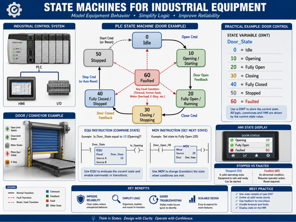
Command = output action4. Example Door State Machine
A simple industrial door may use these states:
0  = Idle
10 = Opening
20 = Fully Open
30 = Closing
40 = Fully Closed
50 = Stopped
60 = Faulted
This is very readable.
Instead of asking:
Is Open bit ON?
Is Close bit ON?
Is Stopped bit ON?
Is Fault bit ON?
You can ask:
What is Door_State right now?If:
Door_State = 30Then:
Door is ClosingThis makes troubleshooting much easier.
5. Example Machine State Values
For a general machine, you may use:
0   = Idle
10  = Starting
20  = Running
30  = Stopping
40  = Stopped
50  = Complete
90  = Faulted
For a filling process:
0   = Idle
10  = Waiting for Container
20  = Filling
30  = Settling
40  = Weight Check
50  = Complete
90  = Faulted
For a valve sequence:
0   = Idle
10  = Opening Valve
20  = Valve Open
30  = Closing Valve
40  = Valve Closed
90  = Faulted
The numbers do not have to be exactly these, but they should be consistent and documented.
6. Why Use Numbers Like 0, 10, 20, 30?
Using gaps between state numbers makes it easier to add future states.
Example:
0  = Idle
10 = Opening
20 = Fully Open
30 = Closing
40 = Fully Closed
Later, you may need to add:
15 = Opening Slow Speed
25 = Waiting Before Close
35 = Closing Slow Speed
If you used 1, 2, 3, 4 with no gaps, adding new states is less clean.
Using values like 0, 10, 20, 30 is a common practical style.
7. State Transition Logic
A transition is the logic that moves the machine from one state to another.
Example:
If Door_State = Idle
AND Open_Request = ON
AND Open_Permissive_OK = ON
THEN Door_State = Opening
In ladder concept:
Door_State == 0
AND Open_Request
AND Open_Permissive_OK
MOV 10 Door_State
That means the door moved from:
Idle → OpeningA state machine should clearly define all allowed transitions.
8. Example Door Transitions
For a door:
Idle → Opening
Opening → Fully Open
Opening → Stopped
Opening → Faulted
Fully Open → Closing
Closing → Fully Closed
Closing → Stopped
Closing → Faulted
Stopped → Opening
Stopped → Closing
Any State → Faulted
Faulted → Idle after reset
This makes the machine behavior predictable.
The logic should not allow random transitions.
Example:
Fully Closed → Fully Openshould not happen instantly unless the door actually opens through the Opening state.
9. Command Logic Based on State
Once the state is defined, output command logic becomes cleaner.
Example:
If Door_State = Opening
THEN Open_Motor_Command = ON
If Door_State = Closing
THEN Close_Motor_Command = ONThis prevents outputs from being controlled in many different places.
Example:
Door_State == 10 → DO_Open_Motor = ON
Door_State == 30 → DO_Close_Motor = ON
The state decides the command.
10. Fault Logic in a State Machine
Fault logic becomes clearer with states.
Example:
If Door_State = Opening
AND Open_Limit_Switch does not turn ON within 10 seconds
THEN Door_State = Faulted
AND latch Open_Timeout_Fault
Another example:
If Door_State = Closing
AND Photoeye becomes blocked
THEN Door_State = Stopped or Opening, depending on design
Faults should normally:
Stop motion
Latch a fault bit
Move machine to Faulted state
Display fault on HMI
Require reset after correction
Example:
Door_State = 60 FaultedThis tells the HMI and technician exactly what condition the door is in.
11. Stopped State vs Faulted State
Stopped and Faulted are not the same.
Stopped
Stopped means the machine was stopped intentionally or paused.
Example:
Operator pressed Stop
Opposite direction command requested Halt
Manual stop active
The machine may be allowed to continue after a new command.
Faulted
Faulted means an abnormal condition occurred.
Example:
Motor overload
Feedback missing
Limit switch timeout
Safety dropped
VFD fault
Faulted usually requires correction and reset.
Simple difference:
Stopped = intentional or controlled stop
Faulted = abnormal condition
This difference is very important for professional logic.
12. State Machine and HMI Status
A state machine is very useful for HMI displays.
Instead of showing many confusing bits, the HMI can show:
Machine Status: Opening
Machine Status: Closing
Machine Status: Fully Open
Machine Status: Faulted
Machine Status: Stopped
Example HMI mapping:
Door_State = 0  → Idle
Door_State = 10 → Opening
Door_State = 20 → Fully Open
Door_State = 30 → Closing
Door_State = 40 → Fully Closed
Door_State = 50 → Stopped
Door_State = 60 → Faulted
This helps operators and technicians understand the machine quickly.
13. State Machine in RSLogix 500
In RSLogix 500, you may use an integer file like:
N7:0 = Door_StateExample:
N7:0 = 0   Idle
N7:0 = 10  Opening
N7:0 = 20  Fully Open
N7:0 = 30  Closing
N7:0 = 40  Fully Closed
N7:0 = 50  Stopped
N7:0 = 60  Faulted
Common instructions:
EQU
MOV
NEQ
GRT
LES
Example:
EQU N7:0 0
XIC Open_Request
XIC Open_Permissive_OK
MOV 10 N7:0
This means:
If Door_State is Idle and Open is requested, move state to Opening.14. State Machine in Studio 5000
In Studio 5000, you may use a DINT tag.
Example:
Door_State : DINTState values:
0  = Idle
10 = Opening
20 = Fully_Open
30 = Closing
40 = Fully_Closed
50 = Stopped
60 = Faulted
Tags may include:
Door_State
Door_Open_Request
Door_Close_Request
Door_Open_Permissive_OK
Door_Close_Permissive_OK
Door_Open_Command
Door_Close_Command
Door_Fault_Active
Studio 5000 also allows more advanced structures, but a DINT state value is a very clear and practical way to learn.
15. Example State Machine Structure
A clean structure may look like this:
1. Input Buffering
2. Requests
3. Permissives
4. Interlocks
5. State Transitions
6. Commands by State
7. Feedback Monitoring
8. Fault Logic
9. Output Buffering
10. HMI Status
This is very professional because the sequence decisions are in one place.
Recommended idea:
Keep state transitions together.
Keep output commands based on state.
Keep faults clearly separated.
This helps troubleshooting.
16. Example: Conveyor State Machine
A conveyor may use states like:
0  = Idle
10 = Starting
20 = Running
30 = Stopping
40 = Stopped
60 = Faulted
Transitions:
Idle → Starting when Start_Request and Permissives_OK
Starting → Running when Running_Feedback is ON
Starting → Faulted if feedback timeout occurs
Running → Stopping when Stop_Request
Running → Faulted if overload trips
Stopping → Stopped when feedback is OFF
Stopped → Starting when Start_Request
Faulted → Idle after Reset and fault cleared
This structure is cleaner than random start/stop bits scattered everywhere.
17. Example: Filler State Machine
A filler may use:
0  = Idle
10 = Waiting for Bottle
20 = Bottle In Position
30 = Filling
40 = Settling
50 = Verify Fill
60 = Index Out
70 = Complete
90 = Faulted
This is useful because fillers often require sequences.
Each state has one job.
Example:
State 30 = FillingDuring this state:
Open fill valve
Monitor flow or weight
Stop when target reached
Move to Settling state
This makes the process easier to understand and troubleshoot.
18. Common Mistakes with State Machines
Mistake 1 — Too many states
Not every small condition needs its own state.
Keep states meaningful.
Mistake 2 — No documented state list
If the state values are not documented, technicians will not know what they mean.
Mistake 3 — Output commands scattered everywhere
Outputs should be based clearly on states and final output logic.
Mistake 4 — Missing fault transitions
Every motion or sequence should have fault conditions.
Mistake 5 — Allowing conflicting states
The machine should not be opening and closing at the same time.
Mistake 6 — No HMI state display
If the HMI does not show the state, operators lose one of the biggest benefits.
19. Best Practices
Use these best practices:
Use one main state tag per equipment or sequence.
Use documented numeric values.
Leave gaps between state numbers.
Keep transition logic together.
Use clear permissives before transitions.
Use interlocks to block unsafe transitions.
Use timers for timeout faults.
Use feedback to prove state completion.
Base commands on state.
Show current state on HMI.
Use faulted state for abnormal conditions.
Use stopped state for intentional stops.
Comment every state transition rung.
The goal is clarity.
A state machine should make the program easier, not harder.
20. Technician Troubleshooting Method
When troubleshooting a state machine, ask:
What is the current state?
What state should it go to next?
What transition condition is missing?
Is a permissive false?
Is an interlock active?
Is a fault latched?
Is feedback missing?
Did the timer timeout?
Is the HMI showing the correct state?
Example:
Door_State = 10 OpeningBut the door is not moving.
Check:
Is Open_Command ON?
Is output ON?
Is motor starter energized?
Is overload OK?
Is feedback present?
Is open limit switch already active?
This method gives direction to troubleshooting.
21. Technician Checklist
When reviewing or troubleshooting a state machine, verify:
State tag exists and is documented.
Current state is visible online.
HMI displays current state.
State transitions are grouped.
Each transition has clear conditions.
Permissives are checked before motion.
Interlocks are checked during operation.
Fault transitions exist.
Timeout timers exist for motion.
Feedback confirms state completion.
Commands are based on state.
Outputs are buffered.
Stopped and Faulted are separate.
Reset logic is safe.
Rung comments explain transitions.
Final Thoughts
State machines are one of the most professional ways to control industrial sequences in PLC logic.
They make machine behavior clear.
They help prevent conflicting commands.
They make HMI status easier to understand.
They make troubleshooting more logical.
Instead of many random bits, the technician can ask:
What state is the machine in?
What condition is needed to move to the next state?
That question alone can simplify troubleshooting.
A state machine organizes machine behavior into clear states, controlled transitions, and predictable actions.
For automation technicians, learning state machines is a major step toward understanding professional PLC programming and industrial sequence control.