1. Why Buffer PLC I/O? Understanding I/O Mapping in Studio 5000
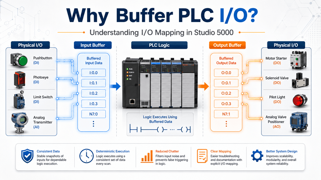
When working with Allen-Bradley ControlLogix or CompactLogix systems, one of the first architectural decisions a programmer eventually faces is how to handle physical I/O inside the PLC program.
At the beginning, it is very common to use the physical module tags directly.
For example:
Local:1:I.Data.0
Local:1:I.Data.1
Local:2:O.Data.0
This works.
The PLC can read the input and control the output without any additional logic.
However, as a machine grows, using physical I/O references everywhere can make the program harder to understand, troubleshoot, maintain, and modify.
This is where concepts such as I/O Mapping, I/O Buffering, and Alias Tags begin to matter.
Although these terms are sometimes used interchangeably, they are not exactly the same thing.
This article introduces the basic idea of PLC I/O buffering and explains why many industrial programs create a software layer between the physical hardware and the control logic.
What Is Physical I/O?
A PLC communicates with field devices through input and output modules.
Typical field inputs include:
- Pushbuttons
- Limit switches
- Photoeyes
- Pressure switches
- Motor overload contacts
- VFD status signals
- Analog transmitters
- Temperature sensors
Typical outputs include:
- Motor starters
- Solenoid valves
- Pilot lights
- Horns
- VFD run commands
- Analog speed references
- Control valve commands
In Studio 5000, a module may expose tags similar to:
Local:1:I.Data
Local:2:O.Data
A specific digital input could therefore be referenced directly:
Local:1:I.Data.0Technically, nothing prevents the programmer from using this tag throughout the entire control program.
For a small training program, that may be perfectly acceptable.
For a large industrial machine, it can quickly become difficult to manage.
The Problem With Direct I/O References
Imagine troubleshooting a warehouse door and seeing this instruction:
XIC Local:1:I.Data.3What does bit 3 represent?
A photoeye?
An overload?
A limit switch?
A safety relay?
The technician may need to open the I/O configuration, check drawings, search comments, or trace the signal before understanding what the rung is doing.
Now compare it with:
XIC DI_Door_Open_LSThe intention is immediately clearer.
This is one of the main reasons industrial programs introduce an intermediate software layer between the physical I/O and the application logic.
What Is I/O Mapping?
I/O mapping means associating a physical I/O point with a meaningful application tag.
Conceptually:
Physical Input
      ↓
Application Tag
For example:
Local:1:I.Data.0
        ↓
DI_Start_PB
The control logic then uses:
DI_Start_PBinstead of repeatedly referencing:
Local:1:I.Data.0The exact implementation can vary.
Common methods include:
- Alias tags
- Individual XIC/OTE mapping
- MOV instructions
- COP instructions
- CPS instructions
- UDT-based mapping
These methods are not identical, and later articles in this series will compare them in detail.
What Is I/O Buffering?
I/O buffering goes one step further.
Instead of allowing the control logic to work directly with the physical module data, the program copies or transfers the I/O information into internal controller tags.
Conceptually:
Physical I/O
     ↓
I/O Buffer
     ↓
Control Logic
For inputs:
Physical Input Module
        ↓
Input Buffer Routine
        ↓
Application Logic
For outputs:
Application Logic
        ↓
Output Buffer Routine
        ↓
Physical Output Module
This creates a clear boundary between:
hardware-level data
and
machine-level logic
That separation is one of the major benefits of buffering.
Example: Direct I/O
Consider a motor start circuit.
The physical inputs are:
Local:1:I.Data.0    Start Pushbutton
Local:1:I.Data.1    Stop Pushbutton
Local:1:I.Data.2    Motor Feedback
Local:1:I.Data.3    Motor Overload
A direct-I/O program might contain:
XIC Local:1:I.Data.0
XIO Local:1:I.Data.1
XIO Local:1:I.Data.3
OTE Local:2:O.Data.0
It works.
But the control logic is tightly connected to the physical I/O architecture.
If the input card moves from Slot 1 to Slot 4, several physical references may need to change.
Example: Buffered I/O
Now create internal tags:
DI_Start_PB
DI_Stop_PB
DI_Motor_FB
DI_Motor_OL

DO_Motor_Run
The input mapping routine could contain:
Local:1:I.Data.0 → DI_Start_PB
Local:1:I.Data.1 → DI_Stop_PB
Local:1:I.Data.2 → DI_Motor_FB
Local:1:I.Data.3 → DI_Motor_OL
The application logic now uses:
DI_Start_PB
DI_Stop_PB
DI_Motor_FB
DI_Motor_OL
And the output routine maps:
DO_Motor_Run → Local:2:O.Data.0The application logic no longer needs to know where the physical motor starter is connected.
Hardware Layer vs Application Layer
This is an important architectural concept.
A well-structured PLC program often separates the system into layers.
For example:
┌──────────────────────────────┐
│ Physical I/O Modules         │
└──────────────┬───────────────┘
               ↓
┌──────────────────────────────┐
│ Input Mapping / Buffering    │
└──────────────┬───────────────┘
               ↓
┌──────────────────────────────┐
│ Signal Processing            │
│ Debounce / Validation        │
└──────────────┬───────────────┘
               ↓
┌──────────────────────────────┐
│ Application Logic            │
│ Requests / Permissives       │
│ Interlocks / State Machines  │
└──────────────┬───────────────┘
               ↓
┌──────────────────────────────┐
│ Output Commands              │
└──────────────┬───────────────┘
               ↓
┌──────────────────────────────┐
│ Output Mapping / Buffering   │
└──────────────┬───────────────┘
               ↓
┌──────────────────────────────┐
│ Physical Outputs             │
└──────────────────────────────┘
This architecture can make troubleshooting significantly easier.
A Useful Programming Rule
A common programming philosophy is:
Only the I/O mapping routines should directly reference physical module tags.
For example, only routines such as:
R01_Input_Buffer
R10_Output_Buffer
would contain references such as:
Local:1:I.Data
Local:2:O.Data
The rest of the program would use meaningful application tags.
For example:
DI_Photoeye
DI_Motor_FB
DO_Motor_Run
This approach makes it easier to change hardware without rewriting large portions of the application logic.
Why This Helps Troubleshooting
Imagine a machine where the conveyor will not start.
Without structured tags, you may need to interpret:
Local:3:I.Data.7
Local:4:I.Data.2
Local:5:I.Data.11
With meaningful tags, the troubleshooting path may immediately show:
DI_Start_PB
DI_Safety_OK
DI_VFD_Ready
DI_Motor_OL
The PLC program begins to describe the machine instead of describing the wiring.
That difference becomes increasingly important as the system grows.
I/O Buffering Is Not the Same as Alias Tags
This distinction is extremely important.
Suppose we create:
DI_Start_PBas an Alias for:
Local:1:I.Data.0The program can now use:
DI_Start_PBinstead of the physical tag.
This improves readability.
However, no new data location has been created.
Conceptually:
DI_Start_PB
      │
      └────── Local:1:I.Data.0
Both names point to the same data.
An Alias Tag therefore provides abstraction and readability, but it is not necessarily an independent I/O buffer.
A true buffering architecture normally creates another controller tag containing a transferred copy or representation of the physical signal.
We will examine this difference much more closely in the next article.
Why Input Updates Matter in Logix Controllers
Another important consideration is that ControlLogix and CompactLogix systems do not behave exactly like older PLC architectures where programmers often imagine all physical inputs being read once at the beginning of the scan.
Logix controllers communicate with I/O modules using connections that may update according to parameters such as the:
Requested Packet Interval — RPI
Because I/O communication and application tasks can operate asynchronously, physical module data may change independently of the execution of a particular routine.
This does not automatically mean every application requires elaborate buffering.
However, understanding that I/O communication can be asynchronous helps explain why data consistency and program architecture become important in larger systems.
Later in this series we will discuss when instructions such as:
COPand:
CPSbecome relevant.
Buffering Does Not Fix Everything
I/O buffering should not be confused with signal filtering.
Suppose a mechanical pushbutton produces contact bounce.
Copying the physical input into another tag does not eliminate the bounce.
Likewise:
Physical Input
      ↓
Buffer Tag
does not automatically provide:
- Debounce
- Noise filtering
- Signal validation
- Fault detection
- Scaling
Those functions belong to additional processing layers.
For example:
Physical Input
      ↓
Raw Buffer
      ↓
Debounce
      ↓
Validated Signal
      ↓
Control Logic
This distinction will become especially important when we discuss analog signals.
What About Analog I/O?
Analog I/O introduces additional considerations.
An analog transmitter may provide:
4–20 mAwhich enters an analog input module.
The program may then need to process:
Raw Data
   ↓
Scaling
   ↓
Engineering Units
   ↓
Signal Validation
   ↓
Process Value
For example:
AI_TankPressure.Raw
AI_TankPressure.EU
AI_TankPressure.BadSignal
An analog output may travel in the opposite direction:
Operator Setpoint
      ↓
Engineering Units
      ↓
Limits
      ↓
Scaling
      ↓
Analog Output Buffer
      ↓
Physical Output
Analog buffering deserves its own article because it involves much more than simply copying a value.
Is I/O Buffering Always Better?
Not necessarily.
There is no universal rule saying that every PLC program must use a complex buffering architecture.
For a very small machine, direct references or Alias Tags may be completely reasonable.
For a large production system, a structured I/O layer can provide major advantages.
The correct decision depends on factors such as:
- Project size
- Number of I/O points
- Hardware architecture
- Maintainability requirements
- Troubleshooting needs
- Team programming standards
- Scan-time requirements
- Modularity
- Future expansion
The important goal is not to blindly follow a programming pattern.
The goal is to understand the engineering tradeoffs behind each method.
The Main Benefits of I/O Buffering
A well-designed I/O layer can improve:
Readability
DI_Conveyor_PEis easier to understand than:
Local:3:I.Data.5Hardware independence
Application logic does not need to know the exact slot and channel used by the physical device.
Troubleshooting
Technicians can quickly identify meaningful machine signals.
Maintenance
Hardware changes can often be handled primarily inside the I/O mapping routines.
Standardization
Large projects can follow a common structure.
Simulation
Internal tags can often be manipulated or substituted more easily during testing.
Scalability
The same architecture can expand into:
- UDTs
- AOIs
- Equipment modules
- State machines
- Diagnostic structures
A Simple Industrial Architecture
A practical structure might look like this:
MainRoutine

    JSR R01_Input_Buffer
    JSR R02_Request_Logic
    JSR R03_Permissives
    JSR R04_Interlocks
    JSR R05_Command_Logic
    JSR R06_Fault_Logic
    JSR R07_Alarm_Logic
    JSR R08_HMI_Status
    JSR R10_Output_Buffer
The physical I/O stays near the boundaries of the application.
The machine logic remains in the middle.
That separation makes the program easier to navigate and understand.
Final Thought
I/O buffering is not simply about replacing an ugly tag name.
It is about creating an intentional boundary between:
the physical machine
and
the software controlling the machine.
Direct I/O references, Alias Tags, MOV instructions, COP, CPS, and UDT-based architectures can all be valid tools.
The important question is:
Which method provides the best balance of readability, maintainability, data integrity, and performance for the application?
That is exactly what we will explore throughout this series.
Next Article
Direct I/O vs Alias Tags vs Mapped Tags in Studio 5000
In the next post, we will compare three of the most common ways to represent PLC I/O and examine an important misconception:
An Alias Tag is not necessarily an I/O buffer.