2. Direct I/O vs Alias Tags vs Mapped Tags in Studio 5000
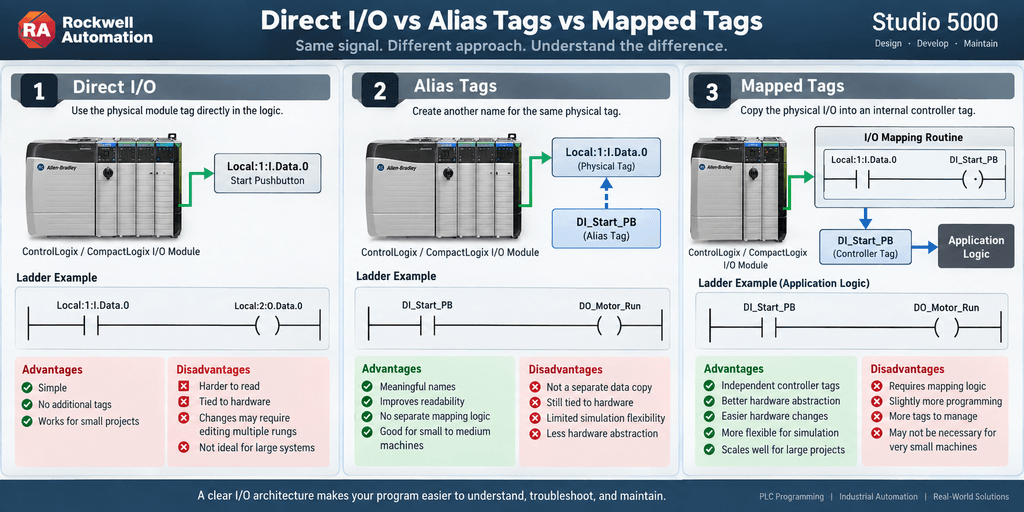
In the first article of this series, we introduced the idea of separating physical PLC I/O from application logic.
Now we can address one of the most common questions in Allen-Bradley programming:
Should I use direct physical I/O references, Alias Tags, or mapped controller tags?
All three methods can work.
But they do not provide the same architecture.
More importantly:
An Alias Tag is not the same thing as an I/O buffer.
Understanding this distinction is important when building PLC programs that are intended to be maintained for years.
The Three Basic Approaches
Assume we have a digital input module located in Slot 1.
The physical input for a Start Pushbutton is:
Local:1:I.Data.0We could use that signal in three common ways.
Direct I/O
XIC Local:1:I.Data.0Alias Tag
DI_Start_PB
Alias For Local:1:I.Data.0
Then the logic uses:
XIC DI_Start_PBMapped Tag
The physical input is copied into an internal controller tag:
Local:1:I.Data.0
        ↓
DI_Start_PB
Then the application logic uses:
XIC DI_Start_PBAt first glance, Alias and Mapping may look identical inside the ladder logic.
Internally, however, they are very different.
Method 1 — Direct Physical I/O
The simplest method is to reference the module directly.
Example:
Local:1:I.Data.0If this input represents a Start Pushbutton:
XIC Local:1:I.Data.0may directly participate in machine logic.
For a very small machine, this may be acceptable.
Advantages of Direct I/O
Direct I/O has several advantages.
Simple
No additional tags or mapping routines are required.
Minimal programming
The programmer can begin using the hardware immediately.
Easy for small training projects
If the entire PLC program contains only a few I/O points, additional abstraction may not provide much benefit.
Little additional execution logic
There is no separate mapping rung required simply to transfer the signal.
Disadvantages of Direct I/O
The disadvantages become more noticeable as the project grows.
Imagine seeing this rung during troubleshooting:
XIC Local:3:I.Data.7
XIO Local:4:I.Data.2
XIC Local:5:I.Data.11
OTE Local:7:O.Data.4
The technician has to determine what every physical reference represents.
Compare that with:
XIC DI_Start_PB
XIO DI_Motor_OL
XIC DI_Safety_OK
OTE DO_Conveyor_Run
The second version communicates much more information immediately.
Hardware Dependency
Direct I/O also couples the control logic directly to the hardware configuration.
Suppose this signal:
Local:1:I.Data.0moves to another input module.
It may become:
Local:5:I.Data.6If the physical reference appears throughout the program, every occurrence may need to be located and changed.
That can increase maintenance effort and the possibility of mistakes.
Method 2 — Alias Tags
Alias Tags are very common in Studio 5000.
Suppose the physical input is:
Local:1:I.Data.0We create:
DI_Start_PBand define it as:
Alias For:
Local:1:I.Data.0
The program can now use:
XIC DI_Start_PBThis is much easier to understand.
But there is an important architectural detail.
What an Alias Tag Really Does
An Alias Tag does not normally create a second independent storage location containing a copied value.
Instead, the alias provides another name for the same underlying data.
Conceptually:
DI_Start_PB
       │
       └──────────────→ Local:1:I.Data.0
The two names ultimately refer to the same physical signal.
Therefore:
Alias Tags improve naming and readability, but they do not automatically create an I/O buffer.
This distinction is extremely important.
Alias Tag Example
Physical input:
Local:1:I.Data.3Create:
DI_Door_Open_LSas an Alias Tag.
Now we can program:
XIC DI_Door_Open_LSinstead of:
XIC Local:1:I.Data.3That is a major readability improvement.
However, the application logic is still ultimately connected directly to the module data.
Advantages of Alias Tags
Alias Tags provide several useful benefits.
Excellent readability
Instead of:
Local:1:I.Data.3we see:
DI_Door_Open_LSNo separate mapping logic
We do not need an additional rung just to transfer the signal.
Easy troubleshooting
The meaningful device name appears directly in ladder logic.
Convenient for smaller machines
A program can remain simple without exposing raw physical addresses throughout the logic.
Limitations of Alias Tags
Alias Tags also have limitations.
The biggest architectural limitation is that they do not fully separate the application from the hardware.
Conceptually:
Application Logic
       ↓
Alias Tag
       ↓
Physical I/O
The alias makes the reference easier to read, but it still points to the hardware.
Alias Tags and Simulation
Another consideration appears during simulation and testing.
Suppose:
DI_Motor_FBis an Alias for:
Local:1:I.Data.4Trying to manipulate the tag for simulation can become less convenient because the tag is directly tied to physical module data.
With an independent internal tag, the software architecture can provide more flexibility.
For example:
Physical Input
      ↓
Raw Tag
      ↓
Simulation Selection
      ↓
Validated Signal
This becomes useful when creating sophisticated simulation environments.
Method 3 — Mapped Controller Tags
With I/O mapping, we create an independent controller tag and transfer the physical signal into it.
Example:
Local:1:I.Data.0
        ↓
DI_Start_PB
Unlike an Alias Tag, DI_Start_PB can now represent a separate data location.
The application logic reads:
DI_Start_PBinstead of directly referencing the physical module.
Example Digital Input Mapping
Physical I/O:
Local:1:I.Data.0Internal tag:
DI_Start_PBA simple mapping rung may conceptually look like:
Local:1:I.Data.0
------] [----------------( )------
                        DI_Start_PB
The application logic uses:
DI_Start_PBThe physical module reference remains inside the I/O mapping routine.
The Architectural Difference
This is the key difference.
Alias
Application Logic
       ↓
DI_Start_PB
       ↓
Local:1:I.Data.0
The alias is essentially another name for the physical signal.
Mapping
Local:1:I.Data.0
       ↓
Mapping Routine
       ↓
DI_Start_PB
       ↓
Application Logic
Now there is a software boundary between the module and the machine logic.
A Better Way to Visualize It
Direct I/O
FIELD DEVICE
     ↓
I/O MODULE
     ↓
CONTROL LOGIC
Alias Tag
FIELD DEVICE
     ↓
I/O MODULE
     ↓
ALIAS NAME
     ↓
CONTROL LOGIC
Mapped Tag
FIELD DEVICE
     ↓
I/O MODULE
     ↓
I/O MAPPING LAYER
     ↓
APPLICATION TAG
     ↓
CONTROL LOGIC
That extra layer is what gives mapped architectures much of their flexibility.
Example: Warehouse Door
Suppose we have the following hardware:
Local:1:I.Data.0    Open Pushbutton
Local:1:I.Data.1    Close Pushbutton
Local:1:I.Data.2    Stop Pushbutton
Local:1:I.Data.3    Open Limit Switch
Local:1:I.Data.4    Closed Limit Switch
And outputs:
Local:2:O.Data.0    Motor Up
Local:2:O.Data.1    Motor Down
Direct I/O Version
The machine logic may contain references such as:
Local:1:I.Data.0
Local:1:I.Data.3
Local:2:O.Data.0
It works.
But the machine logic is directly tied to the module layout.
Alias Version
We could create:
DI_Open_PB
DI_Close_PB
DI_Stop_PB
DI_Open_LS
DI_Closed_LS

DO_Motor_Up
DO_Motor_Down
Each one aliases the corresponding physical I/O point.
The ladder becomes much easier to read.
For example:
XIC DI_Open_PB
XIO DI_Open_LS
OTE DO_Motor_Up
This is much better from a readability perspective.
Mapped Version
Now create independent tags:
DI_Open_PB
DI_Close_PB
DI_Stop_PB
DI_Open_LS
DI_Closed_LS

DO_Motor_Up
DO_Motor_Down
Then place physical module references only inside dedicated I/O routines.
For example:
R01_Input_Mappingcontains:
Local:1:I.Data.0 → DI_Open_PB
Local:1:I.Data.1 → DI_Close_PB
Local:1:I.Data.2 → DI_Stop_PB
Local:1:I.Data.3 → DI_Open_LS
Local:1:I.Data.4 → DI_Closed_LS
Then:
R10_Output_Mappingcontains:
DO_Motor_Up   → Local:2:O.Data.0
DO_Motor_Down → Local:2:O.Data.1
The rest of the PLC program never needs to know where those physical signals are wired.
Hardware Replacement Example
Suppose the Open Limit Switch moves from:
Local:1:I.Data.3to:
Local:4:I.Data.7With Direct I/O, every instance of the physical reference may need to be changed.
With an Alias Tag, the alias relationship may need to be updated.
With a mapped architecture, only the mapping layer may need to change:
OLD

Local:1:I.Data.3
        ↓
DI_Open_LS
becomes:
NEW

Local:4:I.Data.7
        ↓
DI_Open_LS
The machine logic can remain:
DI_Open_LSThat is a major architectural advantage.
Why Mapping Helps Troubleshooting
Imagine troubleshooting a conveyor.
The application logic contains:
DI_Start_PB
DI_Stop_PB
DI_VFD_Ready
DI_VFD_Fault
DI_Motor_FB
DO_VFD_Run
The technician can immediately understand the signals involved.
Then, if necessary, the technician can go to:
R01_Input_Mappingto determine where each signal originates physically.
This creates a useful separation between two troubleshooting questions.
Machine logic question
Why does the conveyor not run?
Hardware question
Which physical input provides the VFD Ready signal?
A well-organized PLC program helps answer both questions quickly.
Mapping Does Not Automatically Mean Better
It is important not to turn mapping into a rigid rule.
Consider a machine with only:
5 Inputs
3 Outputs
Creating multiple UDTs, routines, structures, simulation layers, diagnostic layers, and mapping logic may be unnecessary.
Sometimes simplicity is the better engineering decision.
The correct architecture should match the size and requirements of the machine.
Processor Performance
A common question is:
Which method is better for PLC processor performance?
In most normal industrial applications, this should not be the first design criterion.
Direct references and Alias Tags require little additional application logic.
Individual mapping adds instructions that must execute.
However, modern Logix controllers can normally execute large amounts of simple Boolean mapping logic very quickly.
For many machines, the architectural benefits of clean mapping are more important than the small execution cost of several mapping instructions.
The calculation changes when dealing with systems containing:
- Thousands of I/O points
- Very fast periodic tasks
- Motion applications
- High-speed packaging
- Large numbers of communication structures
- Extremely aggressive scan-time requirements
In those systems, architecture and execution time should be evaluated carefully.
Later in this series we will compare mapping methods from a processor-performance perspective.
What About COP?
Instead of mapping each signal individually:
Input0 → Tag0
Input1 → Tag1
Input2 → Tag2
Input3 → Tag3
we may sometimes copy a larger block of data.
For example:
COP
Source: ModuleInputData
Destination: InputBuffer
Length: ...
This can make large mapping routines much more compact.
However, COP introduces important considerations involving:
- Data types
- Element length
- Structure layout
- Source and destination size
- Data consistency
For that reason, COP deserves its own article.
What About CPS?
Another instruction available in Logix systems is:
CPSor:
Synchronous Copy
At first glance, COP and CPS look very similar.
They are not identical.
CPS becomes important when maintaining the consistency of a complete data set during a transfer matters.
This becomes particularly relevant when discussing asynchronous data updates and communication structures.
We will explore that later in the series.
What About Analog I/O?
The same architectural question also applies to analog signals.
For example:
Local:2:I.Ch0Datacould be used directly.
Or it might feed a structured analog tag:
AI_Tank_Level.Rawwhich is then processed into:
AI_Tank_Level.EUand eventually used by the process logic.
Conceptually:
Analog Input Module
        ↓
Raw Input
        ↓
I/O Mapping
        ↓
Scaling
        ↓
Validation
        ↓
Engineering Units
        ↓
Process Logic
Analog I/O introduces additional layers that digital I/O often does not require.
Later in this series we will build this architecture step by step.
Direct vs Alias vs Mapping
Here is a simplified comparison.
| Feature | Direct I/O | Alias Tag | Mapped Tag |
|---|---|---|---|
| Easy to create | Excellent | Excellent | Good |
| Readability | Poor to Moderate | Excellent | Excellent |
| Independent data location | No | No | Yes |
| Hardware abstraction | Poor | Moderate | Excellent |
| Simulation flexibility | Limited | Limited | Excellent |
| Extra mapping logic | None | None | Required |
| Troubleshooting clarity | Moderate | Excellent | Excellent |
| Large-project scalability | Limited | Good | Excellent |
This table is intentionally simplified.
The best method depends on the application.
So Which Method Should You Use?
A useful guideline is:
Small training project
Direct I/O may be perfectly acceptable.
Small production machine
Alias Tags may provide an excellent balance between simplicity and readability.
Medium or large industrial system
A dedicated I/O mapping layer often becomes much more attractive.
Highly modular architecture
Mapped tags combined with:
UDTs
AOIs
Equipment Modules
State Machines
Diagnostics
Simulation
can provide a very scalable design.
One Important Rule
Whichever architecture is selected, consistency matters.
A program becomes difficult to maintain when one programmer uses:
Local:1:I.Data.0another uses:
DI_Start_PBanother uses:
Motor01.Input.Startand another maps the same physical signal into:
Start_Commandwithout a defined standard.
A good PLC architecture should answer:
Where does physical I/O enter the software architecture?
and:
Which tags should the application logic use?
Once those rules are defined, they should be applied consistently.
Practical Recommendation
For industrial programs, I prefer thinking in terms of layers:
PHYSICAL I/O
      ↓
I/O INTERFACE LAYER
      ↓
APPLICATION SIGNALS
      ↓
CONTROL LOGIC
The exact implementation of the I/O interface may vary.
It could use:
Alias Tags
Individual Mapping
COP
CPS
UDTs
or a combination of techniques.
The important objective is to create a program that technicians can understand, troubleshoot, and safely modify years after the original programmer has left.
Final Thought
Direct I/O, Alias Tags, and mapped controller tags can all produce a working PLC program.
But they solve different problems.
Direct I/O provides simplicity.
Alias Tags provide meaningful names.
Mapped tags provide an independent software layer between hardware and application logic.
The key distinction is:
Alias changes how we reference the data. Mapping can change how the application receives and organizes the data.
That difference becomes increasingly important as PLC projects grow.
Next Article
MOV, XIC/OTE, and Individual I/O Mapping — Building a Digital I/O Buffer in Studio 5000
In the next article, we will build a complete digital input and output mapping routine and compare the practical methods used to transfer individual I/O points into application tags.