1. Understanding Intrinsic Safety Barriers and Isolated Barriers
From Basic Concepts to Advanced Troubleshooting
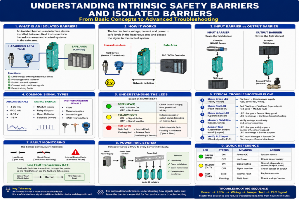
Introduction
In industrial automation, technicians frequently encounter devices installed between field instruments and control systems that are often misunderstood.
These devices are commonly called:
- Intrinsic Safety Barriers
- Isolated Barriers
- Signal Isolators
- Switch Amplifiers
- NAMUR Barriers
Many technicians know they are required for hazardous areas, but few truly understand:
- Why they exist
- How they work
- How inputs differ from outputs
- How to troubleshoot them effectively
This article explains isolated barriers from a practical industrial perspective.
What Is an Isolated Barrier?
An isolated barrier is an interface device installed between:
Field Device
      ↓
Isolated Barrier
      ↓
PLC / DCS / Controller
Its primary functions are:
- Limit energy entering hazardous areas
- Provide galvanic isolation
- Protect control systems
- Convert and condition signals
- Detect wiring faults
Pepperl+Fuchs describes isolated barriers as devices that isolate, amplify, and transform signals while maintaining safe energy levels in hazardous areas.
Why Are They Needed?
Imagine a sensor located near:
- Flammable gases
- Solvents
- Dust
- Fuel vapors
A normal PLC input card can supply enough electrical energy to create:
- Sparks
- Heat
- Ignition sources
An isolated barrier limits:
- Voltage
- Current
- Power
to levels that cannot ignite the atmosphere.
What Is Galvanic Isolation?
One of the most important concepts.
The field side and control side are electrically separated.
Field Sensor
     │
     │
[ Isolation ]
     │
     │
PLC
Benefits:
- Ground loop protection
- Noise reduction
- Surge protection
- Safer fault handling
The signal passes.
The electrical connection does not.
Understanding the Two Sides
Field Side
Connected to:
- NAMUR sensors
- Proximity switches
- Limit switches
- Transmitters
- Solenoid valves
Pepperl+Fuchs refers to this as the field circuit.
Control Side
Connected to:
- PLC inputs
- PLC outputs
- DCS systems
- SCADA systems
Pepperl+Fuchs refers to this as the control circuit.
Input Barriers vs Output Barriers
This is where many technicians become confused.
Input Barrier
Reads a field device.
Example:
NAMUR Sensor
      ↓
Input Barrier
      ↓
PLC Input
The barrier interprets the sensor status and sends a clean signal to the PLC.
Output Barrier
Controls a field device.
Example:
PLC Output
      ↓
Output Barrier
      ↓
Solenoid Valve
The barrier allows the PLC to safely energize devices located in hazardous areas.
Common Signal Types
The K-System supports:
Analog Signals
- 4-20 mA
- 0-20 mA
- 0-10 V
- 1-5 V
Digital Signals
- NAMUR inputs
- Relay outputs
- Open collector outputs
- Solenoid drivers
Instrumentation Signals
- RTDs
- Thermocouples
- Strain gauges
- HART transmitters
Understanding the LEDs
Most troubleshooting starts here.
Pepperl+Fuchs follows NAMUR LED standards.
Green LED (PWR)
ON = Power OK
OFF = No Power
If OFF:
Check:
- 24VDC supply
- Fuse
- Power Rail
- Wiring
Yellow LED (OUT)
ON = Signal Active
OFF = Signal Inactive
Indicates:
- Sensor state
- Relay state
- Output state
depending on module type.
Red LED (CHK)
Most important troubleshooting LED.
Solid Red
Internal module fault.
Possible causes:
- Electronics failure
- Module damage
Replacement is often required.
Flashing Red
External field fault.
Common causes:
- Broken wire
- Short circuit
- Failed sensor
Inspection of field wiring is required.
Fault Monitoring
One of the most powerful features.
The barrier continuously checks:
Line Break
Open WireShort Circuit
Conductors touchingInternal Device Faults
Electronic failureThe system can detect and report these faults automatically.
What Is Line Fault Transparency (LFT)?
Advanced concept.
Normally:
Sensor Faultstays in the field.
With LFT:
Sensor Fault
       ↓
Barrier
       ↓
PLC Receives Fault
The barrier makes field-side faults visible to the controller.
This is extremely useful in troubleshooting.
Typical Troubleshooting Procedure
When a machine suddenly stops:
Step 1
Check Green LED.
No GreenCheck power.
Step 2
Check Red LED.
Flashing
Look for:
- Open wire
- Short circuit
- Sensor failure
Solid
Likely internal module fault.
Step 3
Check Yellow LED.
Operate the sensor manually.
Does the LED change?
YES
Sensor likely good.
NO
Continue troubleshooting.
Step 4
Measure Field Side
Verify:
- Sensor voltage
- Continuity
- Sensor operation
Step 5
Jumper Test
Disconnect sensor.
Install temporary jumper.
Observe:
Yellow LED changesIf yes:
- Barrier OK
- Wiring OK
- Sensor suspect
If not:
- Barrier suspect
Step 6
Verify PLC Input
Check:
PLC Input BitDoes it change when the barrier changes state?
If not:
- Control side wiring issue
- PLC input issue
Power Rail System
Large installations often use Power Rail.
Instead of wiring 24VDC to every barrier individually:
24VDC
   ↓
Power Feed Module
   ↓
Power Rail
   ↓
All Barriers
Benefits:
- Less wiring
- Faster installation
- Easier maintenance
- Collective fault monitoring
Real-World Example
Imagine a NAMUR proximity sensor monitoring a valve position.
Operator reports:
Valve not detectedInvestigation:
- Green LED ON
- Red LED flashing
- Yellow LED OFF
Diagnosis:
Sensor cable brokenRepair cable.
Red LED clears.
System returns to service.
Final Thoughts
An isolated barrier is much more than a safety device.
It serves as:
- Safety interface
- Signal conditioner
- Fault monitor
- Isolation device
- Diagnostic tool
For automation technicians, understanding how signals enter and leave the barrier is essential for troubleshooting hazardous-area instrumentation.
The fastest troubleshooting approach is usually:
Power
→ LEDs
→ Wiring
→ Jumper Test
→ PLC Signal
Mastering this sequence can reduce troubleshooting time from hours to minutes and is a skill expected from experienced industrial instrumentation and automation professionals.