Understanding the Allen-Bradley Guardmaster 440C-CR30 Configurable Safety Relay
Introduction
In industrial automation, machine safety is not optional. Any machine with moving parts, motors, conveyors, pneumatic actuators, guards, doors, or operator access points needs a reliable safety system designed to protect people from hazardous motion.
One device commonly used for this purpose is the Allen-Bradley Guardmaster 440C-CR30 Configurable Safety Relay.
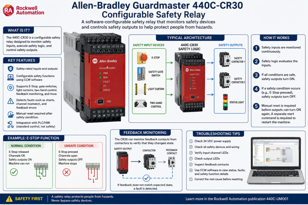
At first glance, it may look like a small PLC because it has inputs, outputs, software configuration, logic blocks, and communication options. However, its purpose is different. The CR30 is not a standard PLC. It is a software-configurable safety relay designed to monitor safety devices and control safety outputs.
According to the Rockwell Automation manual, the 440C-CR30-22BBB is intended to be part of the safety-related control system of a machine and is configured using Connected Components Workbench, also known as CCW.
What Is a Configurable Safety Relay?
A traditional safety relay normally performs one or a few fixed safety functions. For example, it may monitor an E-Stop circuit or a safety gate.
A configurable safety relay goes a step further.
Instead of wiring multiple safety relays together, the CR30 allows different safety functions to be built in software using safety blocks. These blocks can monitor devices such as:
- Emergency stop push buttons
- Safety gate switches
- Light curtains
- Two-hand control stations
- Enabling switches
- Safety mats
- Feedback contacts from contactors
- Reset and restart circuits
The CR30 can monitor multiple safety inputs and then control safety-rated outputs based on the programmed safety logic.
Why the CR30 Is Not a Standard PLC
A standard PLC is normally used for machine control logic:
Start motor
Open valve
Run conveyor
Count bottles
Control sequence
Display machine status
A safety relay or safety controller is used for safety-related control:
Remove power from hazardous motion
Monitor E-Stops
Monitor safety gates
Detect wiring faults
Verify contactor feedback
Prevent automatic restart
This difference is very important.
A PLC may tell a machine to run, but the safety relay is responsible for allowing or removing power to hazardous devices when a safety condition is not satisfied.
In a professional machine design, the PLC should not be the only device stopping hazardous motion. Safety functions must be handled by properly rated safety hardware.
Basic Safety Architecture
A simple machine safety system can be understood like this:
Safety Input Device
        ↓
CR30 Safety Logic
        ↓
Safety Output
        ↓
Contactors / Drives / Power Removal
        ↓
Hazardous Motion Stops
Example:
E-Stop Pressed
        ↓
CR30 Detects Unsafe Condition
        ↓
Safety Output Turns OFF
        ↓
Motor Contactors Drop Out
        ↓
Machine Motion Stops
This is different from a normal PLC stop command. A PLC stop command is part of control logic. A safety stop is part of the safety-related control system.
Main Components of the 440C-CR30 System
The CR30 safety relay includes embedded safety-rated inputs and outputs. It can also accept plug-in modules and can be integrated with communication options depending on the system design. The manual describes the CR30 as having embedded safety-rated inputs and outputs and support for plug-in modules.
1. Safety Inputs
Safety inputs are connected to safety devices such as:
- E-Stops
- Gate switches
- Light curtains
- Safety mats
- Two-hand buttons
- Enabling switches
These inputs are not treated like simple PLC inputs. The CR30 can monitor them for safety behavior, including channel status, discrepancy, and wiring problems depending on the configuration.
2. Safety Logic Blocks
Inside Connected Components Workbench, the safety logic is built using blocks.
Common safety monitoring functions include:
| Safety Function | Purpose |
|---|---|
| Emergency Stop | Monitors E-Stop circuits |
| Gate Switch | Monitors safety doors or guards |
| Light Curtain | Monitors optical safety devices |
| Two-Hand Control | Requires both hands to start hazardous motion |
| Feedback Monitoring | Confirms contactors or external devices actually changed state |
| Reset | Requires a manual reset before safety outputs turn back on |
| Restart | Controls how the system restarts after a safety demand |
The manual lists these safety monitoring functions as part of the CR30 configuration environment.
3. Safety Outputs
Safety outputs are used to control the devices that remove hazardous energy. For example:
- Safety contactors
- Motor contactor coils
- Drive safe torque off circuits, when applicable
- Safety output loops
- Muting lamps or status outputs, depending on the design
A common industrial design uses two contactors in series. The CR30 energizes both contactors only when all safety conditions are satisfied.
Example: E-Stop Safety Function
A basic E-Stop circuit may use two normally closed channels wired into the safety relay.
Normal condition:
E-Stop released
Channel 1 = OK
Channel 2 = OK
CR30 safety logic = OK
Safety outputs = ON
Machine allowed to run
Unsafe condition:
E-Stop pressed
Channel 1 opens
Channel 2 opens
CR30 safety logic = Not OK
Safety outputs = OFF
Machine motion removed
After the E-Stop is released, the machine should not automatically restart. A proper safety system normally requires a manual reset before the safety outputs are restored.
This is a critical concept:
Reset does not mean start. Reset only means the safety circuit is allowed to become ready again.
Reset vs Restart
This is one area that causes confusion for many technicians.
Reset
A reset clears or acknowledges the safety condition after the input device has returned to a safe state.
Example:
E-Stop was pressed
Operator releases E-Stop
Operator presses Reset
Safety relay becomes ready
Restart
Restart means the machine starts moving again.
Example:
Safety relay is ready
Operator presses Start
PLC starts the machine sequence
Motor runs
A safety reset should not automatically start the machine. The operator should still need a separate start command.
A good rule is:
Safety Reset = Make the machine safe-ready
Start Button = Command the machine to run
Feedback Monitoring
Feedback monitoring is one of the most important safety concepts to understand.
The CR30 can monitor feedback contacts from external devices such as contactors. This verifies that the contactors actually changed state when commanded.
Example:
CR30 turns safety output OFF
Contactors should drop out
Feedback contact should change state
If the contactor welds closed or fails mechanically, the feedback signal will not match the expected condition. The CR30 can detect this as a fault depending on the safety configuration.
This is important because the safety relay does not only send a command. It also checks that the external safety devices responded correctly.
What Causes Faults on a Safety Relay?
A safety relay fault is not the same as a normal machine alarm.
A normal alarm may be something like:
Low air pressure
Low product level
Sensor blocked
Cycle timeout
A safety fault may involve:
Input channel mismatch
Cross fault between safety channels
Feedback monitoring fault
Invalid configuration
Plug-in module fault
Internal hardware fault
Safety output fault
The CR30 manual includes a troubleshooting section for recoverable faults, nonrecoverable faults, status indicators, troubleshooting with CCW, and examples such as cross fault analysis.
Solid Red Fault Light: What It Means for a Technician
When a safety relay shows a fault indication, do not treat it like a simple alarm reset.
A solid red fault light usually means the controller has detected a fault condition that must be investigated. The correct response is not just to keep pressing reset.
A technician should check:
- Is 24 VDC power stable?
- Are the safety inputs wired correctly?
- Did an E-Stop, gate switch, or light curtain change state?
- Are both channels of a dual-channel input changing together?
- Is there a short between channels?
- Is there a short to 24 VDC or DC common?
- Are the contactor feedback contacts working correctly?
- Was the configuration recently changed?
- Is there a plug-in module fault?
- Can the fault be seen online in CCW?
Power cycling may temporarily clear a condition, but if the root cause remains, the fault can return. That is why a fault that comes back after a few minutes should be treated as an active troubleshooting problem, not just a reset problem.
Troubleshooting Without a Laptop
When you do not have a laptop connected, troubleshooting is limited but still possible.
Step 1: Observe the LEDs
Check:
Power LED
Run/status LED
Fault LED
Input channel LEDs
Output LEDs
The input LEDs can help identify if a safety device is open, stuck, or not returning to the expected state.
Step 2: Check the Safety Devices
Physically inspect:
E-Stops
Guard doors
Interlock switches
Light curtains
Reset push button
Contactor feedback contacts
Look for loose wires, damaged cables, broken actuators, or misaligned safety switches.
Step 3: Verify 24 VDC
Measure:
24 VDC supply
DC common
Voltage at input terminals
Voltage at output terminals
Do not assume power is good just because one LED is on.
Step 4: Check for External Device Problems
If the safety relay controls contactors, verify that the contactors are physically changing state and that the feedback contacts are not welded, stuck, or miswired.
Troubleshooting With a Laptop and CCW
With Connected Components Workbench, troubleshooting becomes much better because you can go online and view the safety logic.
The CR30 is configured using CCW, and the manual states that the online help is used for configuring the safety functions.
With CCW, a technician can check:
Active safety inputs
Safety block status
Reset block status
Faulted function
Output status
Feedback monitoring
Fault history or diagnostic information
Configuration status
This is the preferred way to troubleshoot recurring faults because it helps identify which safety function is causing the issue.
Important Technician Mindset
When troubleshooting a safety relay, never think only in terms of “how do I reset it?”
Think in this order:
1. What safety function is not satisfied?
2. What input or output is causing the unsafe condition?
3. Is it a real safety demand or a wiring/device fault?
4. Has the root cause been corrected?
5. Is it safe to reset?
6. Does the machine require a separate restart command?
This approach prevents unsafe troubleshooting habits.
Safety Relay vs PLC Alarm
| Item | Safety Relay Fault | PLC Alarm |
|---|---|---|
| Purpose | Protect people from hazards | Notify operator of machine/process issue |
| Reset behavior | Must be corrected before reset | May be acknowledged by HMI |
| Output effect | Removes hazardous motion | May stop process or display warning |
| Risk level | High | Depends on alarm |
| Example | E-Stop channel fault | Low air pressure |
A PLC alarm can tell the operator something is wrong.
A safety relay fault may prevent the machine from running until the safety system is healthy again.
Best Practices for Safety Relay Systems
1. Never Bypass Safety Devices
Do not jumper safety inputs just to make the machine run. If bypassing is required for testing, it must follow plant safety procedures, lockout/tagout rules, and authorized engineering approval.
2. Document the Safety Circuit
A technician should know:
Which input is the E-Stop?
Which input is the gate switch?
Which output controls the contactors?
Which feedback contacts are monitored?
Where is the reset button wired?
3. Label Safety Inputs and Outputs
Good labeling saves troubleshooting time.
Example:
SI_00 = Main E-Stop CH1
SI_01 = Main E-Stop CH2
SI_02 = Guard Door CH1
SI_03 = Guard Door CH2
SO_00 = Safety Contactor K1
SO_01 = Safety Contactor K2
4. Separate Reset From Start
Reset should make the safety system ready.
Start should begin machine motion.
Never design a safety reset that automatically starts the machine.
5. Use Feedback Monitoring
If the safety relay controls contactors, feedback monitoring helps detect welded or failed contactors.
6. Keep a Backup of the Safety Configuration
Because the CR30 is software configurable, the configuration should be backed up and controlled. The manual includes sections related to project backup/restore and reports.
Technician Checklist: Safety Relay Fault
Use this simple checklist when a safety relay is faulted:
[ ] Verify 24 VDC power supply
[ ] Check all E-Stops
[ ] Check all safety gates
[ ] Check light curtains or safety scanners
[ ] Check reset push button
[ ] Check input channel LEDs
[ ] Check output LEDs
[ ] Inspect wiring for shorts or loose terminals
[ ] Check contactor feedback contacts
[ ] Connect with CCW if the fault returns
[ ] Identify the exact faulted safety block
[ ] Correct the root cause before resetting
[ ] Test the safety function after repair
Final Thoughts
The Allen-Bradley Guardmaster 440C-CR30 is more than a simple relay. It is a configurable safety device designed to monitor safety inputs, process safety logic, and control safety-rated outputs.
For automation technicians, understanding this device is very important because many machine problems that look like “PLC issues” are actually safety circuit issues.
A good technician does not simply reset a safety fault. A good technician understands the safety function, checks the inputs, verifies the outputs, confirms feedback, and only resets the system after the root cause is corrected.
In industrial automation, safety logic protects people first. Production comes second.