17. Temperature, Pressure, Level, Flow, and Weight Measurement
Industrial automation is not only about starting motors, reading sensors, or turning outputs ON and OFF.
Many machines and processes need to measure real physical values.
Examples:
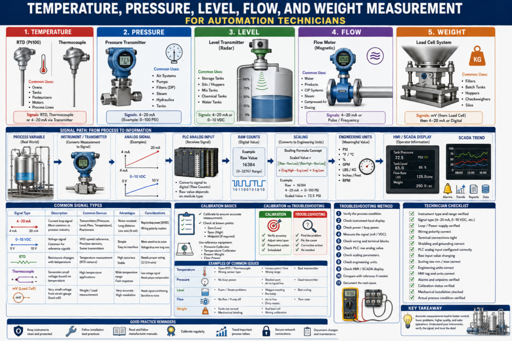
Temperature = 180°F
Pressure = 72 PSI
Tank Level = 65%
Flow = 125 GPM
Weight = 250 lbs
These measurements are critical because they help the PLC, HMI, and SCADA system understand what is happening in the real process.
A PLC can only make good decisions if it receives accurate information from the instruments.
That is why automation technicians must understand the most common process measurements:
Temperature
Pressure
Level
Flow
Weight
These are some of the most important measurements in manufacturing, utilities, batching, filling, packaging, food and beverage, chemical processes, water systems, and many other industries.
1. Why Process Measurements Matter
Process measurements help control and monitor the machine or process.
They are used for:
Automatic control
Operator display
Alarms
Faults
Trends
Reports
Batch records
Quality control
Production monitoring
Safety interlocks
Preventive maintenance
Example:
If pressure is too low, the PLC may stop a pump.
If temperature is too high, the PLC may trigger an alarm.
If tank level is too low, the PLC may prevent a pump from running.
If flow is missing, the PLC may fault the system.
If weight is incorrect, the batch may fail quality checks.
Instrumentation gives the automation system real process information.
2. Temperature Measurement
Temperature measurement is used when the process needs heating, cooling, monitoring, or thermal protection.
Common applications:
Pasteurizers
Ovens
Heat exchangers
Tanks
Process piping
Sealing jaws
Motors
Bearings
Cooling systems
Steam systems
Hot water systems
Common temperature devices include:
RTDs
Thermocouples
Temperature transmitters
Temperature switches
Infrared temperature sensors
RTD
RTD means Resistance Temperature Detector.
An RTD changes resistance as temperature changes.
Common type:
Pt100This means the RTD has 100 ohms at 0°C.
RTDs are commonly used when accuracy and stability are important.
Common applications:
Process tanks
Food and beverage systems
Pasteurization
HVAC systems
Bearing temperature
Water temperature
Thermocouple
A thermocouple produces a small voltage when two different metals are joined and exposed to temperature.
Common thermocouple types:
Type J
Type K
Type T
Type E
Thermocouples are often used for higher-temperature applications.
Common applications:
Ovens
Furnaces
Heaters
Sealing equipment
High-temperature process areas
Temperature Transmitter
A temperature transmitter converts an RTD or thermocouple signal into a standard industrial signal.
Common output:
4–20 mAExample:
4 mA  = 32°F
20 mA = 212°F
The PLC reads the analog signal and scales it into temperature engineering units.
Temperature Troubleshooting
Common temperature measurement problems:
Open RTD
Open thermocouple
Wrong sensor type
Wrong wiring
Loose terminal
Bad transmitter
Wrong scaling
Sensor not inserted correctly
Thermowell issue
Process not contacting sensor
Electrical noise
Bad analog input
Technician checks:
Check sensor type.
Check transmitter display if available.
Check wiring and polarity.
Check PLC raw value.
Check scaling range.
Compare with reference thermometer.
Check if sensor is physically installed correctly.
3. Pressure Measurement
Pressure measurement is used to monitor liquids, gases, air, steam, and hydraulic systems.
Common applications:
Compressed air systems
Water systems
Pumps
Filters
Steam systems
Hydraulic systems
Tanks
Process piping
Clean-in-place systems
Vacuum systems
Common pressure devices include:
Pressure transmitter
Pressure switch
Pressure gauge
Differential pressure transmitter
Vacuum transmitter
Pressure Transmitter
A pressure transmitter converts pressure into an electrical signal.
Common output:
4–20 mAExample:
4 mA  = 0 PSI
20 mA = 100 PSI
The PLC scales the signal into PSI, bar, kPa, or another pressure unit.
Pressure Switch vs Pressure Transmitter
A pressure switch is usually discrete.
Pressure switch = ON/OFFExample:
Air pressure OK = ON
Air pressure low = OFF
A pressure transmitter is analog.
Pressure transmitter = variable measurementExample:
Pressure = 72.5 PSISimple difference:
Switch = condition
Transmitter = value
Differential Pressure
Differential pressure measures the difference between two pressure points.
Common applications:
Filter monitoring
Flow measurement
Tank level
Cleanroom pressure
Air handling systems
Pump performance
Example:
Pressure before filter = 60 PSI
Pressure after filter = 45 PSI
Differential pressure = 15 PSI
A high differential pressure across a filter may mean the filter is clogged.
Pressure Troubleshooting
Common pressure measurement problems:
No loop power
Blocked pressure port
Closed isolation valve
Plugged impulse line
Bad transmitter
Wrong range
Wrong scaling
Air trapped in liquid line
Liquid in gas line
Loose wiring
Bad analog input
Technician checks:
Verify actual process pressure.
Check local gauge.
Check transmitter display.
Check loop current.
Check isolation valves.
Check impulse tubing or pressure port.
Check PLC raw value.
Check scaling.
4. Level Measurement
Level measurement tells the control system how much material is in a tank, hopper, vessel, or silo.
Common applications:
Water tanks
Product tanks
Chemical tanks
Silos
Hoppers
Mix tanks
Holding tanks
Waste tanks
CIP tanks
Level may be displayed as:
Percent
Inches
Feet
Gallons
Liters
Pounds
Kilograms
Common level technologies include:
Ultrasonic level
Radar level
Guided wave radar
Pressure-based level
Float level
Capacitive level
Load-cell-based level
Point level switches
Continuous Level vs Point Level
Continuous Level
Continuous level gives a variable measurement.
Example:
Tank Level = 63%Common signals:
4–20 mA
0–10 VDC
Digital communication
Point Level
Point level is ON/OFF.
Example:
High Level Switch = ON
Low Level Switch = OFF
Simple difference:
Continuous level = how much
Point level = reached or not reached
Ultrasonic Level
Ultrasonic sensors use sound waves to measure distance.
They are often mounted at the top of a tank.
They measure the distance from the sensor to the product surface.
Possible problems:
Foam
Steam
Turbulence
Obstructions
Wrong angle
Condensation
Weak echo
Incorrect range setup
Radar Level
Radar uses electromagnetic waves to measure level.
It is often more reliable than ultrasonic in challenging environments.
Radar can work better with:
Steam
Vapor
Dust
Foam in some cases
Changing temperatures
Longer ranges
Pressure-Based Level
Pressure can be used to estimate liquid level.
The more liquid above the sensor, the higher the pressure.
Common application:
Tank level by hydrostatic pressurePossible problems:
Wrong liquid density
Plugged pressure port
Air trapped in line
Transmitter mounted incorrectly
Incorrect scaling
Level Troubleshooting
Common level measurement problems:
No signal
Wrong range
Foam or turbulence
Sensor blocked
Dirty probe
Wrong density setting
Bad echo
Incorrect mounting
No loop power
Bad scaling
Technician checks:
Verify actual tank level.
Check local display.
Check sensor face or probe.
Check mounting position.
Check loop signal.
Check PLC raw value.
Check scaling.
Check HMI range.
5. Flow Measurement
Flow measurement tells the automation system how much liquid, gas, or steam is moving through a pipe.
Common applications:
Water flow
Product flow
CIP flow
Steam flow
Compressed air flow
Chemical dosing
Filling systems
Cooling water
Pump monitoring
Batching
Common flow units:
GPM
LPM
CFM
SCFM
kg/hr
lb/hr
m³/hr
Common flow meter types:
Magnetic flow meter
Coriolis flow meter
Turbine flow meter
Vortex flow meter
Ultrasonic flow meter
Differential pressure flow meter
Positive displacement flow meter
Magnetic Flow Meter
Magnetic flow meters are commonly used for conductive liquids.
Applications:
Water
Wastewater
Beverages
Chemical solutions
CIP systems
They do not work well with non-conductive fluids like some oils.
Coriolis Flow Meter
Coriolis meters can measure mass flow and density.
They are highly accurate but more expensive.
Common applications:
Batching
Dosing
High-accuracy process measurement
Food and beverage
Chemical processing
Turbine Flow Meter
Turbine meters use a spinning rotor.
They are common in clean liquids and some gases.
Possible issues:
Wear
Debris
Bearing problems
Low-flow inaccuracy
Mechanical damage
Flow Troubleshooting
Common flow measurement problems:
No flow signal
Air in line
Empty pipe
Wrong meter orientation
Dirty meter
Blocked pipe
Pump not running
Valve closed
Wrong scaling
No pulse signal
Bad analog signal
Bad grounding
Technician checks:
Verify actual flow.
Check pump status.
Check valve position.
Check meter display.
Check analog or pulse output.
Check PLC raw value.
Check scaling.
Check pipe condition.
Check grounding, especially for mag meters.
6. Weight Measurement
Weight measurement is commonly used in batching, filling, checkweighing, hoppers, tanks, and silos.
Common applications:
Fillers
Batch tanks
Ingredient systems
Checkweighers
Hoppers
Silos
Scales
Loss-in-weight feeders
Weight is often measured using load cells.
Load Cell
A load cell converts force into a small electrical signal.
This signal is usually very small, often in millivolts.
A typical system may include:
Load Cells
Junction Box
Scale Indicator or Weighing Transmitter
PLC Analog Input or Communication
HMI Weight Display
Example:
Load Cell → Junction Box → Weight Indicator → PLC → HMIThe PLC may receive weight through:
4–20 mA
0–10 VDC
EtherNet/IP
Modbus
Profibus
Serial communication
Tare and Zero
Two important weight terms:
Zero
Tare
Zero
Zero sets the scale reading to zero when there is no load.
Tare
Tare removes the weight of the container or vessel so only the product weight is measured.
Example:
Tank empty weight = 500 lbs
Product weight = 1000 lbs
Gross weight = 1500 lbs
Tare removes tank weight
Net weight = 1000 lbs
Weight Troubleshooting
Common weight measurement problems:
Scale not zeroing
Weight drifting
Unstable reading
One load cell damaged
Junction box issue
Moisture in cable
Mechanical binding
Tank touching pipe or frame
Bad calibration
Wrong span
Loose mounting hardware
Electrical noise
Technician checks:
Check mechanical installation.
Check for binding.
Check load cell cables.
Check junction box.
Check indicator status.
Check zero and tare.
Check calibration.
Compare with known weight.
Check PLC value.
Check HMI scaling.
Important:
Many scale problems are mechanical, not electrical.
If the tank or hopper is touching something, the load cells may not read correctly.
7. Common Signal Types
These instruments may send different signal types to the PLC.
Common signals:
4–20 mA
0–10 VDC
1–5 VDC
Pulse
Frequency
RTD
Thermocouple
Millivolt
EtherNet/IP
Modbus
HART
IO-Link
Examples:
Pressure transmitter → 4–20 mA
Temperature RTD → RTD input or transmitter
Flow meter → 4–20 mA or pulse
Load cell → millivolt to indicator, then 4–20 mA or Ethernet
Level transmitter → 4–20 mA
Always check the instrument documentation.
8. Instrument Range
Every instrument has a range.
Example:
Pressure transmitter range = 0–100 PSI
Level transmitter range = 0–100%
Temperature transmitter range = 32–212°F
Flow meter range = 0–500 GPM
Scale range = 0–5000 lbs
The PLC scaling must match the instrument range.
If the transmitter range and PLC scaling do not match, the HMI value will be wrong.
Example:
Transmitter actual range = 0–150 PSI
PLC scaling = 0–100 PSI
Result:
HMI pressure reading will be incorrect.9. Calibration Basics
Calibration verifies that the instrument reading matches a known reference.
Examples:
Apply 50 PSI and verify transmitter reads 50 PSI.
Apply known temperature and verify reading.
Fill tank to known level and verify level reading.
Run known flow rate and verify meter.
Apply known weight and verify scale.
Calibration checks:
Zero
Span
Linearity
Accuracy
Repeatability
Simple concept:
Zero = low-end adjustment
Span = high-end adjustment
For a 0–100 PSI transmitter:
Zero = 0 PSI
Span = 100 PSI
10. Calibration vs Troubleshooting
Calibration and troubleshooting are related but not the same.
Troubleshooting
Used when something is not working correctly.
Example:
Signal missing
Reading jumping
HMI value wrong
Instrument fault
No loop power
Calibration
Used to verify or adjust accuracy.
Example:
Instrument reads 48 PSI when actual pressure is 50 PSISimple difference:
Troubleshooting = find the problem
Calibration = verify or adjust accuracy
11. Instrumentation Troubleshooting Method
When troubleshooting process instruments, use this method:
1. Understand what the instrument measures.
2. Verify the real process condition.
3. Check local display if available.
4. Check instrument power or loop power.
5. Measure the signal.
6. Check terminal block wiring.
7. Check PLC raw input value.
8. Check PLC scaling.
9. Check HMI engineering units.
10. Compare with a reference if needed.
11. Document the root cause.
This method helps determine whether the problem is:
Process-related
Instrument-related
Wiring-related
PLC-related
Scaling-related
HMI-related
Mechanical-related
12. Common Technician Mistakes
Mistake 1 — Believing the HMI value without verification
The HMI may be wrong because of scaling, tag, or communication issues.
Mistake 2 — Replacing the transmitter too quickly
The issue may be loop power, wiring, scaling, or process conditions.
Mistake 3 — Ignoring mechanical installation
Level, flow, and weight measurements are strongly affected by mechanical installation.
Mistake 4 — Confusing switch and transmitter
A switch is ON/OFF.
A transmitter gives a variable value.
Mistake 5 — Ignoring range
Instrument range and PLC scaling must match.
Mistake 6 — Ignoring shielding and grounding
Analog signals can be affected by noise and poor grounding.
13. Technician Checklist
When working with temperature, pressure, level, flow, or weight instruments, verify:
Instrument type
Process variable
Measurement range
Signal type
Power supply or loop power
Wiring polarity
Terminal block connections
Shielding and grounding
PLC analog input configuration
Raw input value
PLC scaling
Engineering units
HMI display tag
Alarm setpoints
Calibration status
Mechanical installation
Actual process condition
Final Thoughts
Temperature, pressure, level, flow, and weight are some of the most important measurements in industrial automation.
These measurements allow the PLC, HMI, and SCADA system to understand the real process.
A strong automation technician should know how each measurement works, what devices are commonly used, what signal types are involved, and how to troubleshoot from the field instrument to the PLC and HMI.
The basic path is always:
Process Variable → Instrument → Signal → PLC Input → Scaling → Engineering Units → HMI / SCADAWhen troubleshooting, do not guess.
Verify the real process.
Check the instrument.
Measure the signal.
Check the raw value.
Verify scaling.
Confirm the HMI display.
Inspect the mechanical installation.
Instrumentation turns real process conditions into reliable automation data.
Understanding these measurements is a major step toward becoming a more complete automation technician.