5. Motor Control Basics for Automation Technicians
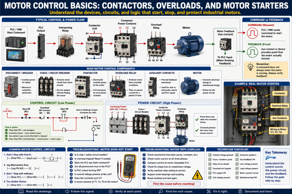
Motor Control Basics: Contactors, Overloads, and Motor Starters
Motors are everywhere in industrial automation.
They move conveyors, pumps, fans, mixers, agitators, compressors, fillers, packaging machines, and many other industrial systems.
Because motors are so common, every automation technician needs to understand the basic devices used to control and protect them.
Before getting deep into PLCs, VFDs, servo drives, and advanced motion control, a technician should understand the foundation:
Contactor
Overload relay
Motor starter
Start/Stop circuit
Seal-in circuit
Auxiliary contacts
Motor feedback
Control circuit
Power circuit
A PLC may send the start command, but the motor still depends on the electrical control circuit and power circuit to operate correctly.
A professional automation technician must understand both.
1. What Is Motor Control?
Motor control means controlling when and how a motor starts, stops, reverses, or runs.
In a basic industrial system, motor control may include:
Start command
Stop command
Safety circuit
Contactor coil
Overload protection
Motor power contacts
Motor feedback
PLC command
HMI command
VFD command
The goal is simple:
Start the motor when conditions are safe and correct, stop the motor when required, and protect the motor from damage.
A basic motor control path looks like this:
Start Command
     ↓
Control Circuit
     ↓
Contactor Coil
     ↓
Power Contacts Close
     ↓
Motor Receives Power
     ↓
Motor Runs
2. Control Circuit vs Power Circuit
Motor circuits usually have two sides:
Control Circuit
Power Circuit
Control Circuit
The control circuit is the low-power side.
It controls the motor starter coil or relay coil.
Common control voltages:
24 VDC
120 VAC
Examples of control circuit devices:
Start push button
Stop push button
E-stop contact
PLC output
Relay coil
Contactor coil
Overload auxiliary contact
Safety relay output
Power Circuit
The power circuit is the high-power side.
It carries the motor current.
Common motor power voltages:
240 VAC
480 VAC
575 VAC
Examples of power circuit devices:
Disconnect
Circuit breaker
Fuses
Contactor power contacts
Overload relay
Motor leads
Motor windings
Basic concept:
Control circuit energizes the contactor coil.
The contactor closes the power circuit.
The power circuit runs the motor.
3. What Is a Contactor?
A contactor is an electrically controlled switch used to turn power loads ON and OFF.
It is commonly used to control motors.
A contactor has two main parts:
Coil
Power contacts
When the coil energizes, the contactor pulls in and closes the power contacts.
When the coil de-energizes, the contactor drops out and opens the power contacts.
Coil ON  → Power contacts close → Motor receives power
Coil OFF → Power contacts open  → Motor loses power
Main parts of a contactor
A1 / A2 coil terminals
L1 / L2 / L3 line terminals
T1 / T2 / T3 load terminals
Auxiliary contacts
Mechanical armature
Example:
L1, L2, L3 = incoming power
T1, T2, T3 = outgoing power to motor
A1, A2     = coil terminals
4. What Is an Overload Relay?
An overload relay protects the motor from excessive current.
It does not protect against all short circuits.
That is the job of fuses or breakers.
The overload relay protects the motor from overheating due to too much current over time.
Common overload causes:
Mechanical jam
Motor overloaded
Pump locked up
Conveyor jammed
Bearing failure
Phase loss
Incorrect overload setting
Motor running above rated current
When the overload trips, it usually opens a normally closed auxiliary contact in the control circuit.
Example:
Overload healthy = NC contact closed
Overload tripped = NC contact opens
This removes power from the contactor coil and stops the motor.
5. What Is a Motor Starter?
A motor starter is the combination of a contactor and overload protection.
Basic motor starter:
Contactor + Overload Relay = Motor StarterThe contactor starts and stops the motor.
The overload relay protects the motor from excessive current.
A basic starter provides:
Motor start control
Motor stop control
Overload protection
Control circuit interface
Auxiliary contacts for feedback
In many control panels, a motor starter is one of the most important components to identify.
6. Start/Stop Circuit
A basic Start/Stop circuit controls the contactor coil.
Typical devices:
Stop push button = normally closed
Start push button = normally open
Overload contact = normally closed
Contactor coil = output load
Auxiliary contact = seal-in contact
Basic control logic:
Control Power
    ↓
Stop PB
    ↓
Overload NC Contact
    ↓
Start PB
    ↓
Contactor Coil
    ↓
Common / Neutral
When the Start button is pressed, the contactor coil energizes.
But when the operator releases the Start button, the motor would stop unless a seal-in contact is used.
7. Seal-In Circuit
A seal-in circuit keeps the contactor energized after the Start button is released.
It uses a normally open auxiliary contact from the contactor.
When the contactor energizes, the auxiliary contact closes and creates an alternate path around the Start push button.
Basic idea:
Press Start
     ↓
Contactor energizes
     ↓
Auxiliary contact closes
     ↓
Coil stays energized after Start is released
Simple representation:
Stop PB NC ---- Overload NC ---- Start PB NO ---- Contactor Coil
                         |------ Aux Contact NO ------|
The auxiliary contact is wired in parallel with the Start push button.
This is one of the most important motor control circuits to understand.
8. Stop Circuit
The Stop push button is normally closed.
When the Stop button is pressed, it opens the circuit and de-energizes the contactor coil.
Stop PB normal = closed
Stop PB pressed = open
When the coil drops out:
Contactor opens
Motor power is removed
Motor stops
Seal-in contact opens
In industrial control, Stop circuits are often wired normally closed because a broken wire or failed connection can stop the machine instead of allowing it to keep running.
9. Auxiliary Contacts
Auxiliary contacts are small contacts mechanically linked to the contactor.
They are not used to carry motor power.
They are used for control and feedback.
Common uses:
Seal-in circuit
PLC motor running feedback
HMI motor status
Interlocking with another starter
Permissive logic
Fault detection
Example:
Contactor pulled in → Auxiliary NO contact closes → PLC input turns ONThis can tell the PLC that the contactor actually energized.
10. Command vs Feedback
This is one of the most important automation concepts.
Command
Command means the PLC or control circuit is asking the motor to run.
Example:
PLC output ON
Motor_Start_Command = TRUE
Feedback
Feedback means there is proof that something actually happened.
Example:
Contactor auxiliary contact closed
VFD running status active
Motor current detected
Motor feedback input ON
Command does not always mean the motor is running.
Example:
PLC output ON, but motor does not run.Possible causes:
Blown fuse
Bad relay
Bad contactor coil
Overload tripped
Safety circuit open
No motor power
Bad contactor
Broken wire
Motor failed
Mechanical jam
A professional technician always separates command from feedback.
11. PLC-Controlled Motor Starter
In modern automation, the PLC often controls the motor starter.
Basic sequence:
Operator presses Start on HMI
        ↓
PLC receives Start_Request
        ↓
PLC checks permissives
        ↓
PLC turns ON motor output
        ↓
Output energizes relay or contactor coil
        ↓
Motor starter pulls in
        ↓
Aux contact sends feedback to PLC
        ↓
PLC confirms motor running
Example control path:
PLC Output → Interposing Relay → Contactor Coil → Motor Starter → MotorExample feedback path:
Contactor Aux Contact → PLC Input → Motor Running Feedback12. Motor Permissives
Before starting a motor, the PLC should check permissives.
Permissives are conditions that must be true before the motor is allowed to start.
Examples:
E-stop healthy
Safety relay healthy
Overload not tripped
VFD healthy
Guard door closed
Air pressure okay
No active motor fault
Downstream equipment ready
Auto mode selected
Basic PLC concept:
Start Request + All Permissives OK = Motor Start CommandIf a permissive is missing, the PLC should not start the motor.
13. Motor Interlocks
Interlocks stop or block the motor when a certain condition becomes active.
Examples:
Jam detected
Guard door opened
Downstream conveyor stopped
Overload tripped
VFD fault active
Safety circuit dropped
Tank level too low
Pressure too high
Permissives allow starting.
Interlocks stop or prevent running.
This distinction helps keep motor logic clean and easier to troubleshoot.
14. Motor Fault Logic
A common PLC fault is a motor feedback fault.
Example:
PLC commands motor to run.
After 3 seconds, feedback is still missing.
PLC latches Motor_Fault.
Motor stops or remains disabled.
Operator must correct issue and reset fault.
Basic logic idea:
Motor_Command ON
AND Motor_Feedback OFF
FOR 3 seconds
= Motor Feedback Fault
This fault helps detect problems such as:
Contactor did not pull in
Overload tripped
Aux contact failed
Broken feedback wire
Output failed
Motor starter problem
15. Basic Troubleshooting: Motor Does Not Start
Problem:
Operator presses Start, but motor does not run.Do not guess.
Follow the path.
Step 1 — Check safety
E-stop reset?
Safety relay healthy?
Guard doors closed?
Light curtain clear?
Step 2 — Check overload
Is the overload tripped?
Is the overload auxiliary contact closed?
Is the overload setting correct?
Step 3 — Check PLC command
Does the PLC see the Start button?
Is the HMI command reaching the PLC?
Are permissives true?
Is a fault latched?
Is the PLC output turning ON?
Step 4 — Check control voltage
Is 24 VDC or 120 VAC present in the control circuit?
Is the fuse good?
Is the common/neutral present?
Step 5 — Check relay or contactor coil
Is voltage reaching A1/A2?
Is the coil the correct voltage?
Is the coil open?
Does the contactor pull in?
Step 6 — Check power circuit
Is line voltage present at L1/L2/L3?
Is voltage present at T1/T2/T3 when contactor pulls in?
Are fuses good?
Is disconnect ON?
Step 7 — Check motor and load
Is motor mechanically jammed?
Is the coupling locked?
Is the conveyor jammed?
Are bearings seized?
Is motor current too high?
16. Basic Troubleshooting: Motor Starts Then Trips
Problem:
Motor starts but trips overload.Possible causes:
Mechanical overload
Jammed conveyor
Pump blocked
Bad bearing
Motor drawing too much current
Phase loss
Incorrect overload setting
Wrong motor wiring
Low voltage
Motor winding issue
Frequent starts
Good checks:
Measure motor current on each phase.
Compare current to motor nameplate FLA.
Check mechanical load.
Check voltage on all phases.
Check overload setting.
Inspect motor and gearbox.
17. Common Mistakes New Technicians Make
Mistake 1 — Assuming PLC output ON means motor is running
PLC output ON only means the PLC is commanding the circuit.
You still need feedback.
Mistake 2 — Resetting overload without finding the cause
An overload trips for a reason.
Find out why.
Mistake 3 — Ignoring the control circuit
Many motor issues are caused by a missing control voltage, bad relay, blown fuse, or open interlock.
Mistake 4 — Ignoring the power circuit
The contactor may pull in, but the motor may still not receive proper voltage.
Mistake 5 — Not checking mechanical load
A motor can trip because the machine is mechanically jammed, not because the electrical circuit is bad.
18. Technician Checklist
When troubleshooting a motor starter, verify:
E-stop and safety circuit healthy
Overload not tripped
Control voltage present
PLC start command active
PLC output turning ON
Relay or contactor coil receiving voltage
Contactor pulls in
Auxiliary feedback changes state
Line voltage present at L1/L2/L3
Load voltage present at T1/T2/T3
Motor current is normal
Motor mechanically free
Correct overload setting
No loose terminals
No blown fuses
No active PLC fault
Final Thoughts
Motor control is one of the most important foundations for automation technicians.
PLCs, HMIs, and SCADA systems may send commands, display alarms, and monitor status, but the motor still depends on real electrical devices to operate.
A technician must understand:
How the contactor works
How the overload protects the motor
How the starter controls motor power
How the seal-in circuit holds the motor ON
How auxiliary contacts provide feedback
How PLC commands differ from real motor feedback
How to troubleshoot from command to coil to motor power
The key is to follow the system logically.
Do not assume the PLC is the problem.
Do not replace parts without testing.
Do not reset overloads without checking why they tripped.
Follow the signal.
Verify the command.
Check the control circuit.
Check the power circuit.
Confirm the feedback.
Find the root cause.
A motor does not run because the PLC says so. A motor runs when the complete control circuit and power circuit are healthy.