14. Sensor Wiring Best Practices for Industrial Automation (14 of 41)
In industrial automation, a sensor can be good, the PLC input card can be good, and the logic can be correct — but the machine can still fail because of poor wiring.
Sensor wiring is one of the most important details in reliable automation.
A loose connector, broken cable, missing common, incorrect PNP/NPN wiring, voltage drop, electrical noise, or bad terminal connection can cause:
PLC inputs flickering
Intermittent sensor faults
False product detection
Missed counts
Random machine stops
Incorrect sequence timing
Analog signal noise
Communication faults
Unstable troubleshooting symptoms
A professional automation technician must understand not only how sensors work, but also how to wire, inspect, protect, and troubleshoot them correctly.
The goal is simple:
A sensor signal should travel from the field device to the PLC cleanly, reliably, and predictably.
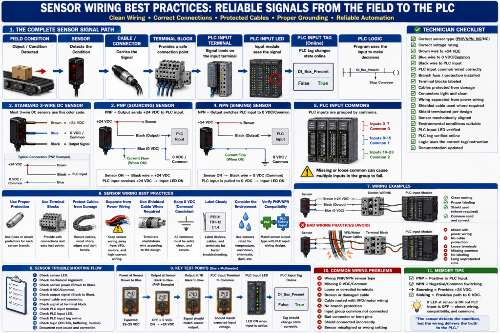
1. The Complete Sensor Signal Path
Every sensor signal has a path.
A typical 3-wire DC sensor path looks like this:
24 VDC Power Supply
        ↓
Fuse / Circuit Protector
        ↓
Terminal Block
        ↓
Sensor Brown Wire
        ↓
Sensor Electronics
        ↓
Sensor Black Output Wire
        ↓
Cable / Connector
        ↓
Terminal Block
        ↓
PLC Input Terminal
        ↓
PLC Input LED
        ↓
PLC Input Tag
        ↓
PLC Logic
And the common return path:
Sensor Blue Wire → 0 VDC / CommonWhen troubleshooting, follow the full path.
Do not only look at the sensor.
Do not only look at the PLC.
The problem can be anywhere between them.
2. Use the Correct Sensor Type
Before replacing or installing a sensor, verify the exact type.
Check:
Voltage rating
PNP or NPN output
Normally open or normally closed
Light operate or dark operate
Connector type
Pinout
Sensing distance
Target material
Environmental rating
Response time
Analog or discrete output
Never replace a sensor only because it “looks the same.”
Two sensors can look identical but have different outputs.
Example:
Old sensor = PNP Normally Open
New sensor = NPN Normally Open
The new sensor may power up and detect the target, but the PLC input may not turn ON.
3. Understand the Standard 3-Wire DC Sensor Colors
Many industrial 3-wire DC sensors use this color code:
Brown = +24 VDC
Blue  = 0 VDC / Common
Black = Output Signal
Typical connection:
Brown → +24 VDC
Blue  → 0 VDC / Common
Black → PLC Input
However, always verify the datasheet or wiring diagram.
Do not assume every sensor uses the same color code, especially with specialty sensors, older devices, imported equipment, or multi-output sensors.
4. Verify PNP/NPN Compatibility
PNP and NPN must match the PLC input wiring design.
PNP Sensor
PNP = sensor output sends +24 VDC to PLC inputCommon wiring:
Sensor brown → +24 VDC
Sensor blue  → 0 VDC
Sensor black → PLC input
PLC input common → 0 VDC
NPN Sensor
NPN = sensor output switches PLC input to 0 VDC/commonCommon wiring:
Sensor brown → +24 VDC
Sensor blue  → 0 VDC
Sensor black → PLC input
PLC input common → +24 VDC
A simple rule:
PNP output usually works with sinking PLC input.
NPN output usually works with sourcing PLC input.
If the sensor LED turns ON but the PLC input does not, always check PNP/NPN compatibility.
5. Protect Sensor Circuits with Proper Fusing
Sensor circuits should be protected.
A shorted sensor cable should not take down the entire machine if the panel is designed correctly.
Good practice:
Main 24 VDC protection
Branch protection for sensor groups
Separate protection for PLC/I/O
Separate protection for solenoids and relays
Separate protection for analog instruments when needed
Example:
Branch 1 = PLC CPU and I/O
Branch 2 = Photoeyes
Branch 3 = Proximity sensors
Branch 4 = Solenoids and relays
Branch 5 = Analog instruments
This makes troubleshooting easier.
If one sensor cable shorts, only that branch should trip instead of killing the entire 24 VDC system.
6. Use Terminal Blocks as Test Points
Terminal blocks are extremely useful.
They provide a clean place to land field wires and test signals.
A sensor may be wired like this:
PE101 Brown → TB1-10 = +24 VDC
PE101 Blue  → TB1-11 = 0 VDC
PE101 Black → TB1-12 = PLC input signal
During troubleshooting, you can check:
Signal at sensor
Signal at field connector
Signal at terminal block
Signal at PLC input
If the signal is present at the sensor but missing at the terminal block, the problem is in the field cable or connector.
If the signal is present at the terminal block but missing at the PLC, the problem is inside the panel wiring or input module.
7. Label Wires and Devices Clearly
Good labels save time.
A professional installation should include:
Sensor device tag
Cable label
Terminal block number
Wire number
PLC input address or tag
Drawing reference
Junction box label
Connector label
Example:
PE101 = Product Present Photoeye
Cable = CBL-PE101
PLC Input = Local:1:I.Data.4
Terminal = TB1-12
Without labels, troubleshooting becomes slower and riskier.
With labels, the technician can follow the drawing and signal path with confidence.
8. Protect Sensor Cables from Physical Damage
Sensor cables often fail because of mechanical damage.
Common causes:
Cable rubbing against machine frame
Cable crushed by guards
Cable pulled too tight
Cable hanging near conveyors
Cable pinched in doors
Cable damaged by washdown
Cable exposed to heat
Cable bent too sharply
Connector hit by product or tooling
Best practices:
Use proper cable routing
Use cable tray or wireway where possible
Use strain relief
Avoid sharp bends
Avoid pinch points
Avoid moving parts
Secure cables with proper clips
Use protective conduit where required
Leave service loop when appropriate
Keep connectors accessible
A good technician always inspects cable condition before replacing the sensor.
9. Avoid Routing Sensor Cables with High-Power Wiring
Sensor signals are low-level control signals.
They can be affected by electrical noise.
Avoid routing sensor cables next to:
VFD output cables
Motor leads
High-current power wiring
Welding cables
Heater power wiring
Large solenoid wiring
Transformer primary wiring
High-voltage wiring
Better practice:
Separate signal wiring from power wiring.
Cross power wiring at 90 degrees if needed.
Use separate wire duct when possible.
Use shielded cable for sensitive signals.
Follow manufacturer and plant standards.
This is especially important for:
Analog signals
Encoder signals
High-speed counters
Vision system triggers
Communication cables
Low-level instrumentation
10. Use Shielded Cable When Required
Shielded cable helps protect signals from electrical noise.
Common applications:
Analog transmitters
4–20 mA loops
0–10 VDC signals
Thermocouples
RTDs
Encoders
High-speed sensors
Vision triggers
Communication cables
VFD motor cables
The shield or drain wire should be terminated according to the design.
Important:
Do not randomly ground shield wires.
Do not cut shield wires without understanding their purpose.
Do not connect shields at multiple points unless the design requires it.
Follow drawings and manufacturer recommendations.
Incorrect shield grounding can cause noise or ground loop problems.
11. Keep 0 VDC/Common Consistent
Many sensor problems are common problems.
A sensor may have +24 VDC, but if the 0 VDC/common is missing or incorrect, the circuit may not work.
Check:
Sensor blue wire connected to correct 0 VDC common
PLC input common wired correctly
Power supply common stable
Common jumpers installed correctly
Input group common connected
No loose common terminals
If multiple sensors fail together, suspect a shared common, shared fuse, or shared terminal jumper.
12. Use Proper Connectors
Many industrial sensors use M8 or M12 connectors.
Connector problems are very common.
Check for:
Loose connector
Bent pins
Water inside connector
Corrosion
Damaged threads
Connector not fully seated
Wrong pinout
Wrong cable type
Broken wire near connector
Best practices:
Hand-tighten correctly
Use the correct connector type
Avoid over-tightening
Use washdown-rated connectors where needed
Use proper cable length
Avoid putting stress on connector body
Keep connector away from impact points
A bad connector can look like a bad sensor.
13. Consider the Environment
The sensor and cable must match the environment.
Check for:
Washdown
Chemicals
High temperature
Cold temperature
Vibration
Oil
Dust
Humidity
Product buildup
Mechanical impact
Food-grade requirements
Explosion hazardous areas
A sensor that works in a clean dry area may fail quickly in a wet washdown area.
Important ratings:
IP rating
NEMA rating
Temperature rating
Chemical resistance
Cable jacket material
Hazardous area rating if applicable
14. Keep Sensor Mounting Solid
Wiring is not only electrical.
Mechanical installation matters too.
A sensor may fail because the bracket moves.
Check:
Loose bracket
Sensor misalignment
Vibration
Target moving out of range
Reflector loose
Sensor too close or too far
Incorrect angle
Mechanical damage
For photoeyes:
Clean the lens.
Check alignment.
Check reflector.
Check sensitivity or teach setting.
For proximity sensors:
Check sensing distance.
Check target material.
Check flush or non-flush mounting requirements.
A perfectly wired sensor can still fail if it is physically misaligned.
15. Avoid Overloading Sensor Outputs
Sensor outputs have current limits.
A sensor output is usually designed to feed a PLC input, not a large load.
Do not use a sensor output to directly power devices unless the sensor is rated for it.
Check:
Sensor output current rating
PLC input current requirement
Any connected relay coil
Load type
Short-circuit protection
Manufacturer specifications
If a sensor must switch a larger load, use an interposing relay or input module as designed.
16. Separate Discrete and Analog Wiring When Needed
Discrete sensors are usually ON/OFF.
Analog sensors carry variable measurements.
Analog signals are more sensitive to wiring issues.
For analog wiring:
Use shielded cable where required.
Avoid routing near VFD/motor wiring.
Keep connections tight.
Follow polarity carefully.
Verify loop power.
Check signal common.
Avoid ground loops.
Use proper analog input card configuration.
A noisy analog level or pressure signal can cause unstable process control.
17. Document Sensor Replacements
When replacing a sensor, document:
Old part number
New part number
Reason for replacement
Wiring changes
Teach or sensitivity setting
PLC input tested
Machine function tested
Date and technician
This helps future troubleshooting.
If a wrong sensor type is installed, documentation can help identify what changed.
18. Best Practice Troubleshooting Method
When troubleshooting a sensor, follow this order:
1. Understand what the sensor should detect.
2. Check sensor LED.
3. Check mechanical alignment.
4. Check sensor power.
5. Check 0 VDC/common.
6. Check output signal.
7. Check connector and cable.
8. Check terminal block.
9. Check PLC input LED.
10. Check PLC input tag online.
11. Check logic using the input.
12. Document root cause.
This avoids random troubleshooting.
19. Common Sensor Wiring Mistakes
Mistake 1 — Replacing the sensor without checking the cable
A damaged cable or connector can cause the same symptom as a bad sensor.
Mistake 2 — Mixing PNP and NPN
A wrong output type may power up but fail to turn ON the PLC input.
Mistake 3 — Forgetting the common
The circuit needs a complete return path.
Mistake 4 — Routing sensor cables next to VFD output wiring
This can cause noise and intermittent signals.
Mistake 5 — Not checking input group common
Several PLC inputs may share one common terminal.
Mistake 6 — Ignoring environment
Washdown, vibration, heat, oil, dust, and product buildup can damage sensors and cables.
Mistake 7 — Not labeling wires
Poor labeling makes future troubleshooting much harder.
20. Technician Checklist
Use this checklist for reliable sensor wiring:
Correct sensor type selected
Voltage rating matches system
PNP/NPN matches PLC input wiring
NO/NC setting verified
Light/dark operate setting verified
Brown wire to +24 VDC
Blue wire to 0 VDC/common
Black wire to PLC input
PLC input common wired correctly
Branch fuse or circuit protection good
Terminal blocks labeled
Cable protected from physical damage
Connector tight and clean
No water or corrosion in connector
Sensor cable separated from power wiring
Shielded cable used where required
Shield terminated according to design
Sensor mechanically aligned
Target within sensing range
PLC input LED verified
PLC tag verified online
Replacement documented
Final Thoughts
Reliable sensor wiring is critical for reliable automation.
A sensor is only useful if its signal reaches the PLC correctly.
The full path matters:
Sensor → Cable → Connector → Terminal Block → PLC Input → PLC Tag → LogicA professional technician does not only replace sensors.
A professional technician checks power, common, output signal, cable condition, connector condition, terminal blocks, PLC input wiring, and the logic path.
Good wiring reduces downtime.
Good labeling speeds troubleshooting.
Good cable routing prevents noise.
Good protection prevents one short from stopping the whole machine.
Good documentation helps the next technician.
The sensor detects the condition, but the wiring delivers the truth to the PLC.