13. Sensor Troubleshooting: When the PLC Does Not See the Input (13 of 41)
One of the most common problems in industrial automation is this:
The sensor detects the target, but the PLC input does not turn ON.Sometimes the sensor LED is ON.
Sometimes the sensor has power.
Sometimes the cable looks good.
Sometimes the PLC input LED stays OFF.
Sometimes the PLC input LED is ON, but the logic still does not respond.
This is why sensor troubleshooting must be done step by step.
Do not guess.
Do not replace the sensor immediately.
Do not assume the PLC input card is bad.
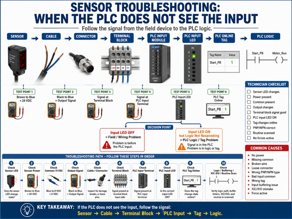
A professional technician follows the signal from the field device to the PLC logic.
Sensor → Cable → Connector → Terminal Block → PLC Input → PLC Tag → PLC LogicThe goal is to find exactly where the signal is lost.
1. Understand the Signal Path
Before troubleshooting, understand how the signal travels.
A typical sensor input path looks like this:
+24 VDC Power Supply
        ↓
Sensor Brown Wire
        ↓
Sensor Electronics
        ↓
Sensor Black Output Wire
        ↓
Field Cable / Connector
        ↓
Terminal Block
        ↓
PLC Input Terminal
        ↓
PLC Input LED
        ↓
PLC Input Tag / Address
        ↓
PLC Logic
And the return path:
Sensor Blue Wire → 0 VDC / CommonIf any part of this path is open, incorrect, loose, damaged, or mismatched, the PLC may not see the input.
2. First Question: Is It a Field Problem or a PLC Logic Problem?
When the PLC does not respond to a sensor, separate the issue into two major areas:
Field / Electrical Problem
PLC / Logic Problem
Field / Electrical Problem
Examples:
Sensor has no power
Missing 0 VDC/common
Broken cable
Wrong PNP/NPN sensor
Loose terminal
Bad connector
Bad PLC input common
PLC input LED does not turn ON
PLC / Logic Problem
Examples:
PLC input LED is ON, but wrong tag is used
Input is buffered incorrectly
Wrong XIC/XIO instruction
Routine is not being scanned
Force is active
Faulted module
HMI is looking at the wrong tag
A very useful rule:
If the PLC input LED does not turn ON, troubleshoot field wiring first.
If the PLC input LED turns ON but logic does not respond, troubleshoot PLC logic.
3. Check the Sensor LED
Most sensors have an LED indicator.
The LED usually tells you if the sensor is detecting the target.
Check:
Does the LED turn ON and OFF when the target appears and disappears?If the LED does not change
Possible causes:
No sensor power
Sensor misaligned
Dirty lens
Target too far away
Wrong sensitivity setting
Wrong teach setting
Bad reflector
Wrong sensor type for the application
Sensor damaged
If the LED does change
That means the sensor is detecting the target.
But it does not prove the PLC is receiving the signal.
Next, check the sensor power and output signal.
4. Check Sensor Power
For a typical 3-wire DC sensor:
Brown = +24 VDC
Blue  = 0 VDC / Common
Black = Output Signal
Measure:
Brown to Blue = approximately 24 VDCExpected:
23–25 VDC in many systemsIf there is no voltage:
Check the 24 VDC power supply.
Check branch fuse or circuit protector.
Check terminal block.
Check cable.
Check connector.
Check 0 VDC/common.
Important:
Do not check only brown to ground. Check brown to blue to verify the actual sensor supply circuit.
The sensor needs both +24 VDC and 0 VDC/common.
5. Check the Sensor Output Signal
After confirming sensor power, check the output.
For a PNP sensor, measure:
Black to BlueTypical result:
Sensor OFF = 0 VDC
Sensor ON  = +24 VDC
For an NPN sensor, the output switches toward 0 VDC/common, so testing depends on the input circuit and wiring design.
The key is to confirm:
Does the black output wire change state when the sensor detects the target?If the sensor LED changes but the output does not change, possible causes include:
Bad sensor output
Wrong sensor mode
Wrong teach configuration
Wrong output wire
Incorrect sensor type
Sensor damaged
6. Check the Cable and Connector
Cables and connectors are common failure points.
Look for:
Cut cable
Crushed cable
Loose M12 connector
Bent connector pins
Water inside connector
Corrosion
Damaged jacket
Cable pulled too tight
Connector not fully seated
Broken wire near sensor head
A sensor can be perfectly good, but the cable can be bad.
This is especially common around:
Conveyors
Moving machine sections
Washdown areas
Cable tracks
Doors
Guarding
Vibration points
7. Check the Terminal Block
Terminal blocks are excellent troubleshooting points.
If the sensor output changes at the sensor but not at the terminal block, the problem is between the sensor and the panel.
Check:
Signal present at sensor output?
Signal present at field connector?
Signal present at terminal block?
If the signal is missing at the terminal block:
Cable problem
Connector problem
Wrong wire landed
Loose terminal
Broken conductor
Bad junction box connection
If the signal is present at the terminal block, continue toward the PLC input.
8. Check the PLC Input Terminal
Measure the signal at the PLC input terminal.
Ask:
Is the correct voltage reaching the PLC input point?If voltage reaches the input terminal but the PLC input LED does not turn ON, check:
PLC input common wiring
Input module power
Input module fuse
Wrong input type
Bad input channel
Faulted input module
Wrong PNP/NPN wiring
This is where understanding sourcing and sinking becomes very important.
9. Check the PLC Input Common
Many input modules have grouped commons.
Example:
Inputs 0–7 share COM0.
Inputs 8–15 share COM1.
If one common is missing, several inputs in the same group may not work.
Symptoms of missing input common:
Several inputs dead
Sensor output voltage present but input LED OFF
Inputs work in one group but not another
PLC input behaves inconsistently
Always check the input module wiring diagram.
Do not assume all PLC input cards are wired the same.
10. Check PNP/NPN Compatibility
If the sensor LED turns ON but the PLC input stays OFF, one of the first things to verify is the sensor output type.
Check the sensor label or part number:
PNP
NPN
Sourcing
Sinking
NO
NC
Light Operate
Dark Operate
Basic rule:
PNP sensor sends +24 VDC to the input.
NPN sensor switches the input to 0 VDC/common.
The PLC input wiring must match the sensor type.
Common mistake:
Replacing a PNP sensor with an NPN sensor that looks physically identical.The sensor may power up and detect the target, but the PLC input may not work.
11. Check the PLC Input LED
The PLC input LED is a very useful diagnostic point.
Input LED OFF
Possible causes:
No signal reaching input
Missing common
Wrong sensor type
Bad wiring
Bad input channel
No field power
Input LED ON
This usually means the PLC input module sees the electrical signal.
If the machine still does not respond, the problem may be in the PLC logic.
Next step:
Go online with the PLC and check the input tag/address.12. Check the PLC Tag or Address Online
The PLC input LED may be ON, but the logic may still not respond.
Check the actual input tag or address online.
Examples:
I:1/4 in RSLogix 500
Local:1:I.Data.4 in Studio 5000
Photoeye_BoxPresent in tag-based logic
Verify:
Does the online input tag change state?
Is the program using the correct tag?
Is there input buffering?
Is the buffered bit changing?
Sometimes the physical input works, but the program uses a different internal bit.
13. Check Input Buffering
Many professional PLC programs do not use raw inputs directly.
Instead, they map raw inputs to internal tags.
Example:
Raw Input: Local:1:I.Data.4
Buffered Tag: DI_Box_Present
The logic uses:
DI_Box_Presentnot the raw input directly.
If the raw input turns ON but the buffered tag does not, check the input mapping rung.
Possible problems:
Wrong raw input mapped
Wrong internal tag
Rung not scanned
XIC/XIO mistake
Input disabled by logic
Copy/paste error
14. Check XIC and XIO Logic
In PLC ladder logic, a common mistake is using the wrong instruction.
In Allen-Bradley style ladder:
XIC = Examine If Closed
XIO = Examine If Open
A normally open field sensor does not automatically mean you always use XIC.
A normally closed field sensor does not automatically mean you always use XIO.
You must think in terms of the PLC bit state.
Ask:
When the condition is healthy or active, is the PLC bit ON or OFF?
What does the logic need to be true?
Example:
Sensor detects box → PLC bit ON
Use XIC if you want logic true when box is present.
Use XIO if you want logic true when box is not present.
15. Check if the Routine Is Being Scanned
Sometimes the input works, but the logic using it is not being executed.
Check:
Is the routine called by JSR?
Is the task running?
Is the program inhibited?
Is the module inhibited?
Is the logic inside an inactive routine?
In RSLogix 500, verify the subroutine is called.
In Studio 5000, verify the routine is scheduled or called in the program.
This is a common issue after program modifications.
16. Check for Forces
A force can override input or output behavior.
If the PLC has forces enabled, the logic may not behave as expected.
Check:
Are forces installed?
Are forces enabled?
Is the input forced ON or OFF?
Is an output forced?
Forces are useful for testing, but they can cause confusion if left active.
Always follow plant procedures before enabling or removing forces.
17. Troubleshooting Example: Sensor LED ON, PLC Input LED OFF
Problem
A photoeye LED turns ON when a box is present, but the PLC input LED stays OFF.
Step-by-step
1. Check brown to blue = 24 VDC.
2. Check black to blue at sensor.
3. Sensor output changes to +24 VDC.
4. Check signal at terminal block.
5. No signal at terminal block.
Root cause
Broken signal wire between sensor and terminal block.Correction
Repair or replace cable.
Verify signal at terminal block.
Verify PLC input LED.
Verify online input tag.
Test machine operation.
Document the repair.
18. Troubleshooting Example: PLC Input LED ON, Logic Not Responding
Problem
PLC input LED turns ON, but the conveyor does not stop.
Step-by-step
1. Check PLC input LED = ON.
2. Go online with PLC.
3. Raw input tag changes state.
4. Buffered input tag does not change.
5. Check input mapping rung.
Root cause
Wrong input address mapped to the internal sensor tag.Correction
Correct input mapping.
Download or edit online following plant procedure.
Test input.
Verify machine response.
Document change.
19. Troubleshooting Example: Multiple Sensors Not Working
Problem
Several sensors on the same PLC input card do not turn ON.
Possible causes:
Missing input common
Blown sensor fuse
Bad 24 VDC branch
Disconnected terminal jumper
Faulted input module
Wrong common group wiring
Step-by-step
1. Check 24 VDC supply.
2. Check sensor branch fuse.
3. Check power at sensors.
4. Check signal at terminal blocks.
5. Check PLC input common.
6. Check input module status.
Root cause example
Input group common wire disconnected.Several sensors failed together because they shared the same common.
20. Common Mistakes New Technicians Make
Mistake 1 — Replacing the sensor first
Always prove the problem before replacing parts.
Mistake 2 — Checking only +24 VDC
A sensor also needs 0 VDC/common.
Mistake 3 — Ignoring the signal wire
The sensor may have power but no output signal.
Mistake 4 — Ignoring PNP/NPN
Wrong output type can prevent the PLC input from turning ON.
Mistake 5 — Not checking the PLC input LED
The input LED tells you if the module sees the electrical signal.
Mistake 6 — Not going online with the PLC
The LED may be ON, but the logic may use the wrong tag or buffered bit.
Mistake 7 — Forgetting forces
Forces can make troubleshooting confusing.
Mistake 8 — Not checking if the routine is scanned
Logic inside a routine that is not called will not execute.
21. Sensor Troubleshooting Checklist
Use this checklist when the PLC does not see a sensor input:
Sensor LED changes with target.
Sensor has correct voltage.
Brown to blue measures approximately 24 VDC.
0 VDC/common is present.
Output signal changes state.
Cable and connector are good.
Terminal block receives signal.
PLC input terminal receives signal.
PLC input common is wired correctly.
PNP/NPN type matches PLC input wiring.
PLC input LED turns ON.
PLC online input tag changes.
Input buffering tag changes.
Correct XIC/XIO instruction is used.
Routine is being scanned.
No forces are interfering.
No module faults or inhibits are active.
Final Thoughts
Sensor troubleshooting is one of the most practical skills an automation technician can develop.
When a PLC does not see an input, do not guess.
Follow the signal.
Sensor → Cable → Terminal Block → PLC Input → PLC Tag → LogicCheck the sensor LED.
Check power.
Check common.
Check the output wire.
Check the terminal block.
Check the PLC input LED.
Check the online tag.
Check the logic.
A sensor problem may be electrical, mechanical, configuration-related, or programming-related.
The key is to prove where the signal is lost.
If the PLC does not see the input, follow the signal from the real world to the logic.
That method will save time, reduce unnecessary parts replacement, and build confidence in real industrial troubleshooting