12. PNP, NPN, Sourcing, and Sinking Made Simple (12 of 41)
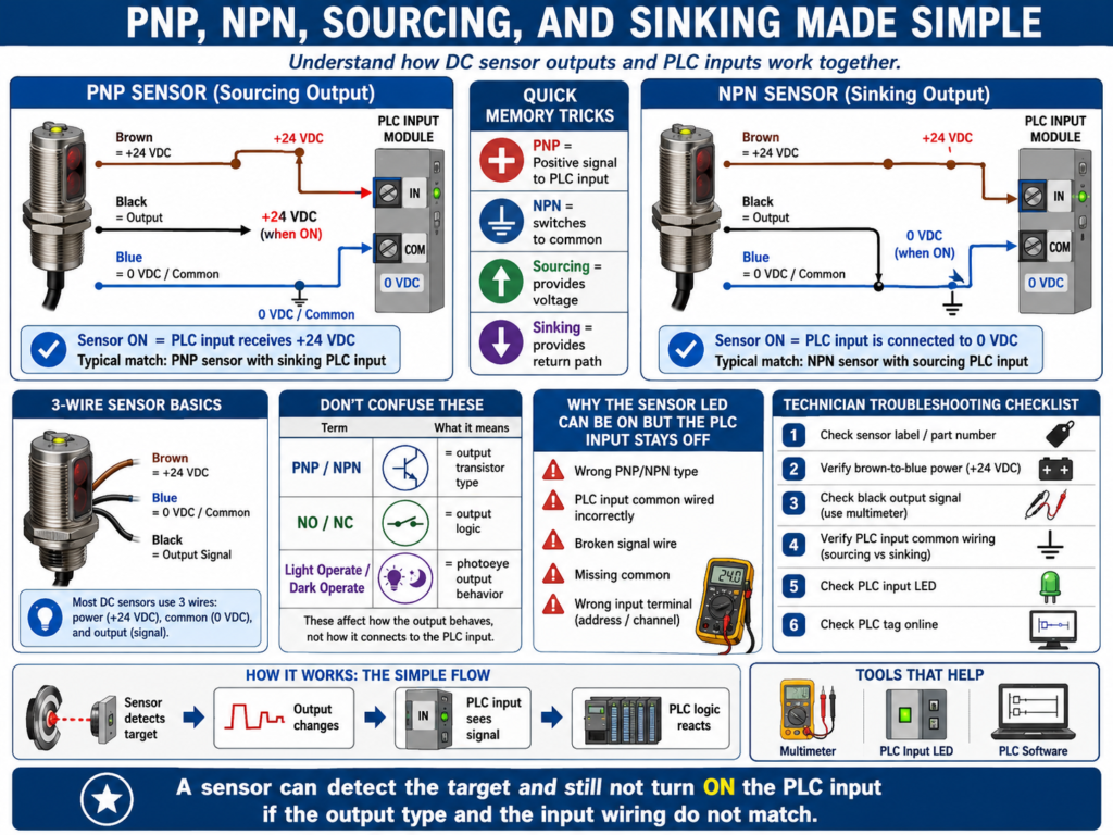
One of the most confusing topics for new automation technicians is the difference between PNP, NPN, sourcing, and sinking.
This confusion usually appears when a sensor has power, the sensor LED turns ON, but the PLC input does not respond.
The sensor may not be bad.
The PLC input module may not be bad.
The problem may be that the sensor output type and the PLC input wiring do not match.
To troubleshoot sensors correctly, every automation technician must understand how current flows between:
+24 VDC
Sensor output
PLC input
0 VDC / Common
Once you understand the path, PNP and NPN become much easier.
1. The Basic 3-Wire DC Sensor
Many industrial DC sensors use three wires:
Brown = +24 VDC
Blue  = 0 VDC / Common
Black = Output signal
Basic wiring:
Brown wire → +24 VDC
Blue wire  → 0 VDC / Common
Black wire → PLC input
The brown and blue wires power the sensor electronics.
The black wire is the output signal that changes state when the sensor detects the target.
The important question is:
When the sensor turns ON, what does the black wire do?That answer determines whether the sensor is PNP or NPN.
2. What Is a PNP Sensor?
A PNP sensor switches positive voltage to the PLC input.
Simple definition:
PNP = Sensor output sends +24 VDC to the PLC input.When the sensor turns ON:
Black output wire = +24 VDCThat means the PLC input receives positive voltage.
Basic idea:
Sensor ON → Output sends +24 VDC → PLC input turns ONPNP sensors are commonly called:
Sourcing sensorsBecause the sensor sources positive voltage to the PLC input.
3. PNP Sensor Current Flow
A simplified PNP current path looks like this:
+24 VDC
   ↓
PNP sensor output
   ↓
PLC input
   ↓
PLC input common
   ↓
0 VDC
The sensor provides the positive voltage.
The PLC input side provides the path back to common.
Simple way to remember:
PNP = Positive signal to the PLC inputOr:
PNP = P for PositiveThis is not a perfect electronics definition, but it is a helpful field memory trick.
4. What Is an NPN Sensor?
An NPN sensor switches the PLC input to common.
Simple definition:
NPN = Sensor output connects the PLC input to 0 VDC / Common.When the sensor turns ON:
Black output wire = connected to 0 VDCThat means the sensor provides the return path to common.
Basic idea:
Sensor ON → Output switches to 0 VDC → PLC input turns ONNPN sensors are commonly called:
Sinking sensorsBecause the sensor sinks current to common.
5. NPN Sensor Current Flow
A simplified NPN current path looks like this:
+24 VDC from PLC input circuit
   ↓
PLC input
   ↓
NPN sensor output
   ↓
0 VDC / Common
In this case, the PLC input circuit usually supplies or references the positive side, and the sensor completes the path to common.
Simple way to remember:
NPN = Negative/common switchingAgain, this is a field-friendly way to remember the concept.
6. Sourcing vs Sinking
The terms sourcing and sinking describe how current flows.
Sourcing
A sourcing device supplies positive voltage.
Sourcing = Provides +24 VDCA PNP sensor is a sourcing output device.
PNP sensor ON → sends +24 VDC outSinking
A sinking device provides a path to common.
Sinking = Provides path to 0 VDCAn NPN sensor is a sinking output device.
NPN sensor ON → connects output to 0 VDC7. Sensor Output vs PLC Input Type
This part is very important.
The sensor output and PLC input module must be compatible.
A simple rule:
Sourcing output needs sinking input.
Sinking output needs sourcing input.
Or:
PNP sensor usually connects to a sinking PLC input.
NPN sensor usually connects to a sourcing PLC input.
Why?
Because current needs a complete path.
One side must source current, and the other side must sink current.
8. PNP Sensor with Sinking PLC Input
This is very common in modern industrial automation.
PNP Sensor
   ↓
Sends +24 VDC to PLC input
   ↓
PLC input common is tied to 0 VDC
   ↓
Input turns ON
Basic wiring:
Sensor brown → +24 VDC
Sensor blue  → 0 VDC
Sensor black → PLC input
PLC input common → 0 VDC
When the sensor turns ON, the input receives +24 VDC and turns ON.
9. NPN Sensor with Sourcing PLC Input
This is also used in some systems.
NPN Sensor
   ↓
Connects PLC input to 0 VDC
   ↓
PLC input circuit provides positive side
   ↓
Input turns ON
Basic wiring:
Sensor brown → +24 VDC
Sensor blue  → 0 VDC
Sensor black → PLC input
PLC input common → +24 VDC
When the sensor turns ON, it completes the path to 0 VDC.
10. Why a Sensor LED Can Turn ON but the PLC Input Stays OFF
This is a very common troubleshooting situation.
The sensor may have power and detect the target.
You see the sensor LED change.
But the PLC input LED does not turn ON.
Possible causes:
Wrong PNP/NPN type
PLC input common wired incorrectly
Broken signal wire
Missing 0 VDC common
Wrong terminal
Bad input module
Wrong sensor output mode
Sensor output damaged
PLC input not compatible with sensor output
The sensor LED only proves the sensor detects the target.
It does not prove that the PLC input is receiving the correct electrical signal.
11. How to Identify if a Sensor Is PNP or NPN
Check the sensor label or datasheet.
Look for markings like:
PNP
NPN
Sourcing
Sinking
NO
NC
Light ON
Dark ON
10–30 VDC
On some sensors, the part number identifies the output type.
Do not rely only on the sensor shape or connector.
Two sensors can look identical but have different outputs.
12. How to Test a PNP Sensor with a Meter
For a typical 3-wire PNP sensor:
Brown = +24 VDC
Blue  = 0 VDC
Black = Output
Step 1 — Check power
Measure:
Brown to Blue = approximately 24 VDCStep 2 — Check output
Measure:
Black to BlueExpected behavior:
Sensor OFF = approximately 0 VDC
Sensor ON  = approximately 24 VDC
If the black wire switches to +24 VDC when the target is detected, it is behaving like a PNP output.
13. How to Test an NPN Sensor with a Meter
For a typical 3-wire NPN sensor:
Brown = +24 VDC
Blue  = 0 VDC
Black = Output
Step 1 — Check power
Measure:
Brown to Blue = approximately 24 VDCStep 2 — Check output
Testing NPN can be slightly more confusing because the output switches to common.
Depending on the input circuit and pull-up path, measuring black to blue may not behave the same as PNP.
A practical way is to test the sensor in the circuit and check whether the PLC input changes.
You can also check the datasheet and wiring diagram to confirm output behavior.
Expected concept:
Sensor ON = black output is pulled toward 0 VDC14. Normally Open vs Normally Closed
PNP and NPN describe the output transistor type.
Normally open and normally closed describe the output logic.
They are different things.
A sensor can be:
PNP Normally Open
PNP Normally Closed
NPN Normally Open
NPN Normally Closed
Normally Open Sensor
No target = output OFF
Target detected = output ON
Normally Closed Sensor
No target = output ON
Target detected = output OFF
So always check both:
Output type: PNP or NPN
Output logic: NO or NC
15. Light Operate vs Dark Operate
Photoelectric sensors may use terms like:
Light Operate
Dark Operate
Light Operate
The output turns ON when the receiver sees light.
Example:
Light received = output ONDark Operate
The output turns ON when the light beam is blocked or not received.
Example:
Beam blocked = output ONThis matters because the sensor may be electrically correct but configured opposite of what the PLC logic expects.
16. PLC Input Common Wiring
PLC input common wiring is critical.
Some input cards are grouped by common terminals.
Example:
Inputs 0–7 share one common.
Inputs 8–15 share another common.
If the common is missing or connected incorrectly, multiple inputs may not work.
Always check:
PLC input module wiring diagram
Input common terminals
Sensor output type
Power supply common
Terminal block wiring
Do not assume every input card is wired the same.
17. Troubleshooting Example: Sensor LED ON, PLC Input OFF
Problem
A proximity sensor LED turns ON when metal is present, but the PLC input does not turn ON.
Step 1 — Check sensor power
Brown to Blue = 24 VDCPower is good.
Step 2 — Check sensor output type
Sensor label says:
NPN NOStep 3 — Check PLC input wiring
PLC input module is wired for PNP/sourcing sensors.
That means the input expects the sensor to provide +24 VDC.
Root cause
Wrong sensor output type for the PLC input wiring.Correction
Replace sensor with correct PNP type, or rewire only if the system design allows it and documentation is updated.
18. Troubleshooting Example: Multiple Inputs Not Working
Problem
Several sensors on the same input module group are not turning ON.
Possible causes:
Missing input common
Blown input group fuse
Wrong common jumper
Loose terminal
Power supply common disconnected
Incorrect wiring after replacement
Troubleshooting path
Check sensor power.
Check signal at each sensor.
Check terminal block.
Check PLC input terminal.
Check input group common.
Check module wiring diagram.
Check input LED.
If multiple inputs fail at once, suspect common or shared power before replacing sensors.
19. Common Mistakes New Technicians Make
Mistake 1 — Thinking brown, blue, black always means the same sensor type
The colors may be standard, but the output type can still be PNP or NPN.
Mistake 2 — Replacing a PNP sensor with an NPN sensor
The sensor may power up and detect, but the PLC input may not work.
Mistake 3 — Ignoring input common wiring
The PLC input common determines how the input card detects voltage/current.
Mistake 4 — Confusing NO/NC with PNP/NPN
NO/NC is output logic.
PNP/NPN is output transistor type.
Mistake 5 — Assuming the sensor LED proves the PLC sees the signal
The sensor LED only proves detection at the sensor.
The PLC input must still receive the correct electrical signal.
Mistake 6 — Not checking the exact part number
A single letter or digit in the sensor part number may indicate PNP, NPN, NO, NC, cable type, connector type, or sensing range.
20. Field Memory Tricks
These are not perfect engineering definitions, but they help in the field:
PNP = Positive signal to PLC input
NPN = Negative/common switching
PNP sources +24 VDC.
NPN sinks to 0 VDC.Sourcing provides voltage.
Sinking provides a return path.Sensor LED ON does not always mean PLC input ON.21. Technician Checklist
When replacing or troubleshooting a DC sensor, verify:
Sensor voltage rating
PNP or NPN output
Sourcing or sinking output
Normally open or normally closed
Light operate or dark operate
Connector type
Pinout
Wire colors
PLC input module type
PLC input common wiring
Terminal block wiring
Sensor power
Output signal at sensor
Signal at PLC input terminal
PLC input LED
PLC input tag online
Final Thoughts
PNP, NPN, sourcing, and sinking can seem confusing at first, but the idea becomes clearer when you follow current flow.
A PNP sensor sends positive voltage to the PLC input.
An NPN sensor switches the PLC input to common.
The PLC input module must be wired to match the sensor output type.
When troubleshooting, do not guess.
Check the sensor label.
Check the part number.
Check the wiring diagram.
Check the PLC input common.
Measure the output signal.
Verify the PLC input LED.
Confirm the online tag.
A sensor can detect the target and still not turn ON the PLC input if the output type and input wiring do not match.
Understanding PNP and NPN is one of the most practical sensor skills an automation technician can learn.