4. Reading Electrical Schematics and Control Drawings (4 of 41)
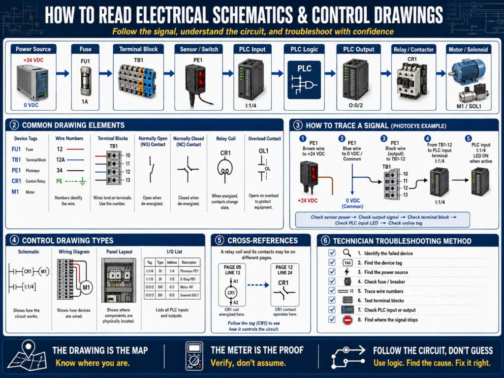
Electrical drawings are one of the most important tools an automation technician can use.
When a machine fails, many technicians immediately go to the PLC program, replace a sensor, reset a VFD, or start checking random terminals inside the panel.
But a professional technician starts with the system documentation.
The drawing tells you how the circuit is supposed to work.
It helps you follow the signal from the power source, through protection devices, switches, relays, terminal blocks, PLC inputs, PLC outputs, and field devices.
A good technician does not guess.
A good technician follows the drawing.
1. Why Electrical Drawings Matter
Electrical drawings help you understand:
Where power comes from
Which fuse protects the circuit
Which wire feeds the device
Which terminal block is used
Which PLC input receives the signal
Which PLC output controls the load
Which relay or contactor is involved
Where the common or neutral returns
What safety devices are in the circuit
Without drawings, troubleshooting becomes guessing.
With drawings, troubleshooting becomes a method.
Example:
Sensor not working
     ↓
Check drawing
     ↓
Find sensor power source
     ↓
Find wire number
     ↓
Find terminal block
     ↓
Find PLC input
     ↓
Test each point
     ↓
Locate where the signal is lost
2. Types of Electrical Drawings
In industrial automation, you may see different types of drawings.
Electrical Schematic
Shows how the electrical circuit works.
It focuses on function.
Example:
Power → Fuse → Stop PB → Start PB → Relay Coil → CommonWiring Diagram
Shows how devices are physically wired.
It focuses on connections.
Example:
Sensor brown wire → Terminal TB1-12
Sensor blue wire → Terminal TB1-13
Sensor black wire → PLC input I:1/4
Panel Layout Drawing
Shows the physical location of devices inside the control panel.
Example:
Power supply located upper left
PLC located center
Terminal blocks located bottom
VFD located right side
Network switch located upper right
I/O List
Shows PLC input and output assignments.
Example:
| PLC Address / Tag | Description | Field Device |
|---|---|---|
I:1/0 | Start Push Button | PB101 |
I:1/1 | Stop Push Button | PB102 |
I:1/4 | Photoeye Product Present | PE101 |
O:2/0 | Conveyor Motor Command | MTR101 |
Network Drawing
Shows communication connections between industrial devices.
Example:
PLC → Stratix Switch → HMI
PLC → Stratix Switch → VFD
PLC → Stratix Switch → Remote I/O
PLC → Stratix Switch → Vision Camera
3. Basic Electrical Symbols
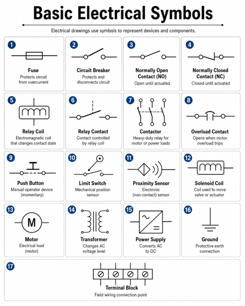
Electrical drawings use symbols to represent devices.
Common symbols include:
You do not need to memorize every symbol immediately.
But you should learn the common ones that appear in control panels every day.
4. Wire Numbers and Device Tags
Wire numbers are extremely important.
They allow you to trace a circuit physically.
Example:
Wire 1201 leaves fuse FU1
Wire 1201 goes to Stop PB
Wire 1202 leaves Stop PB
Wire 1202 goes to Start PB
Wire 1203 leaves Start PB
Wire 1203 goes to relay coil CR1
Device tags identify components.
Examples:
| Tag | Meaning |
|---|---|
FU1 | Fuse 1 |
CB1 | Circuit Breaker 1 |
PS1 | Power Supply 1 |
PB1 | Push Button 1 |
LS1 | Limit Switch 1 |
PE1 | Photoeye 1 |
CR1 | Control Relay 1 |
M1 | Motor 1 |
OL1 | Overload 1 |
SOL1 | Solenoid 1 |
TB1 | Terminal Block 1 |
A device tag should match the drawing, the panel label, and sometimes the PLC tag or HMI description.
5. Terminal Blocks
Terminal blocks are the connection point between the control panel and field devices.
They make troubleshooting easier because you can test signals at a known location.
Example:
Field photoeye PE101
Brown wire → TB1-10 = +24 VDC
Blue wire  → TB1-11 = 0 VDC
Black wire → TB1-12 = Signal to PLC input
When troubleshooting, terminal blocks help you divide the problem:
Is the signal present in the field?
Is the signal present at the terminal block?
Is the signal present at the PLC input?
This helps you know if the problem is in the field wiring, panel wiring, or PLC input module.
6. Reading a Circuit from Left to Right
Many control schematics are read from left to right or top to bottom.
A common control circuit may look like this:
L+ / +24 VDC
     ↓
Fuse
     ↓
Stop Contact
     ↓
Start Contact
     ↓
Relay Coil
     ↓
0 VDC / Common
For troubleshooting, follow the path:
Power source → Protection → Control contacts → Load → Return pathDo not skip around randomly.
Follow the circuit in order.
7. Normally Open vs Normally Closed
This is one of the most important concepts in electrical drawings.
Normally Open Contact
A normally open contact is open in its normal state.
It closes when actuated.
Example:
Start push buttonNormal state:
OpenPressed state:
ClosedNormally Closed Contact
A normally closed contact is closed in its normal state.
It opens when actuated.
Example:
Stop push button
E-stop contact
Overload auxiliary contact
Safety relay feedback
Normal state:
ClosedPressed or faulted state:
OpenImportant:
“Normal” usually means the device is not actuated, not pressed, not energized, or not tripped.
8. Relay Coils and Relay Contacts
Relays are common in control circuits.
A relay has two main parts:
Coil
Contacts
When the coil energizes, the contacts change state.
Example:
CR1 coil energized
     ↓
CR1 normally open contact closes
     ↓
CR1 normally closed contact opens
The coil may be shown on one page and the contacts may be shown on another page.
This is why cross-references are important.
9. Cross-References
Cross-references tell you where related devices are shown in the drawing package.
Example:
CR1 coil shown on page 12, line 4.
CR1 contact shown on page 15, line 8.
A relay contact may not be drawn beside the coil.
A contactor auxiliary contact may be used in a PLC input circuit on a different page.
A safety relay output may appear in multiple circuits.
Cross-references help you find all related parts of the device.
10. PLC Inputs on Electrical Drawings
A PLC input drawing shows how a field signal reaches the input module.
Example:
+24 VDC
   ↓
Photoeye PE101
   ↓
Signal wire
   ↓
Terminal block TB1-12
   ↓
PLC input I:1/4
   ↓
Input module common
When the photoeye turns ON, the PLC input should turn ON.
Troubleshooting path:
Check sensor power.
Check sensor output.
Check terminal block.
Check PLC input LED.
Check PLC online tag.
If voltage reaches the PLC terminal but the input LED does not turn ON, possible causes include:
Bad input module
Wrong common
Incorrect sensor type
Wrong wiring
Input card fault
11. PLC Outputs on Electrical Drawings
A PLC output drawing shows how the PLC controls a field device.
Example:
PLC output O:2/0
     ↓
Relay coil CR1
     ↓
CR1 contact closes
     ↓
Solenoid valve SOL1 energizes
Troubleshooting path:
Is the PLC output LED ON?
Is voltage present at the output terminal?
Is the relay coil energizing?
Is the relay contact closing?
Is voltage reaching the load?
Is the load common/neutral connected?
Is the device mechanically free?
Important:
The PLC output LED only tells you that the module is trying to turn on the output.
It does not always prove that voltage is reaching the final device.
12. Ladder Logic vs Electrical Ladder Diagram
This can confuse new technicians.
There are two types of “ladder” you may hear about:
Electrical Ladder Diagram
This is a drawing of real electrical devices and wiring.
Example:
Stop PB → Start PB → Relay CoilPLC Ladder Logic
This is the program inside the PLC.
Example:
XIC Start_PB OTE Motor_CmdThey look similar, but they are not the same.
Electrical ladder shows physical wiring.
PLC ladder shows logic decisions.
Both are important.
13. How to Trace a Sensor Signal
Example problem:
A photoeye detects a product, but the PLC input does not turn ON.Use the drawing to trace the signal.
Step 1 — Find the sensor on the drawing
Look for:
PE101
Photoeye Product Present
Step 2 — Identify the wires
Typical 3-wire sensor:
Brown = +24 VDC
Blue  = 0 VDC
Black = Output signal
Step 3 — Find the terminal block
Example:
Brown → TB1-10
Blue  → TB1-11
Black → TB1-12
Step 4 — Find the PLC input
Example:
TB1-12 → PLC Input I:1/4Step 5 — Test each point
Brown to blue at sensor = 24 VDC?
Black to blue changes state?
Signal present at TB1-12?
PLC input LED turns ON?
PLC tag changes online?
Now you are troubleshooting logically.
14. How to Trace a Motor Start Circuit
Example problem:
Motor does not start.Use the drawing to identify:
Start command
Stop circuit
E-stop or safety circuit
Overload contact
PLC output
Interposing relay
Contactor coil
Motor power circuit
Feedback contact
Troubleshooting path:
PLC Start command active?
All permissives healthy?
PLC output ON?
Relay coil energized?
Contactor coil energized?
Overload contact closed?
Motor power present?
Motor feedback active?
This is how the drawing connects to PLC troubleshooting.
15. Common Mistakes When Reading Drawings
Mistake 1 — Not checking the drawing revision
Machines are modified over time.
The drawing may be outdated.
Always check revision dates and field modifications.
Mistake 2 — Assuming wire color is always correct
Wire colors help, but wire numbers and drawings are more reliable.
Mistake 3 — Ignoring terminal blocks
Terminal blocks are one of the best troubleshooting points.
Use them.
Mistake 4 — Confusing PLC logic with physical wiring
A PLC tag may be true in logic, but the field device may still not be energized.
Mistake 5 — Not following the return path
Always check the complete circuit, including common, neutral, or ground reference where applicable.
Mistake 6 — Not using cross-references
Relay contacts, contactor auxiliaries, and safety contacts may be on different pages.
16. Practical Troubleshooting Method Using Drawings
Use this method:
1. Identify the failed device or missing signal.
2. Find the device tag on the drawing.
3. Identify the power source.
4. Identify the protective device.
5. Identify all contacts or interlocks in series.
6. Identify the terminal blocks.
7. Identify the PLC input or output.
8. Measure voltage step by step.
9. Find where the signal stops.
10. Document the root cause.
This method works for sensors, relays, solenoids, valves, motors, and many PLC I/O problems.
17. Technician Checklist
When using electrical drawings, verify:
Correct drawing revision
Device tag
Wire number
Terminal number
Power source
Fuse or breaker
PLC address or tag
Common/neutral return
Relay coil and contacts
Cross-references
Safety contacts
Field wiring path
Panel wiring path
Final Thoughts
Electrical schematics and control drawings are not just paperwork.
They are troubleshooting tools.
They show how the machine is supposed to work.
They help you trace power, signals, commands, feedback, interlocks, and outputs.
A strong automation technician knows how to read drawings and use them in the field.
When a machine fails, do not guess.
Find the drawing.
Find the device.
Follow the wire number.
Check the terminal.
Measure the voltage.
Verify the PLC input or output.
Find where the signal stops.
The drawing is the map. The meter is the proof. The technician connects both to find the problem.