3. 24 VDC Control Power: The Backbone of Industrial Automation (3 of 41)
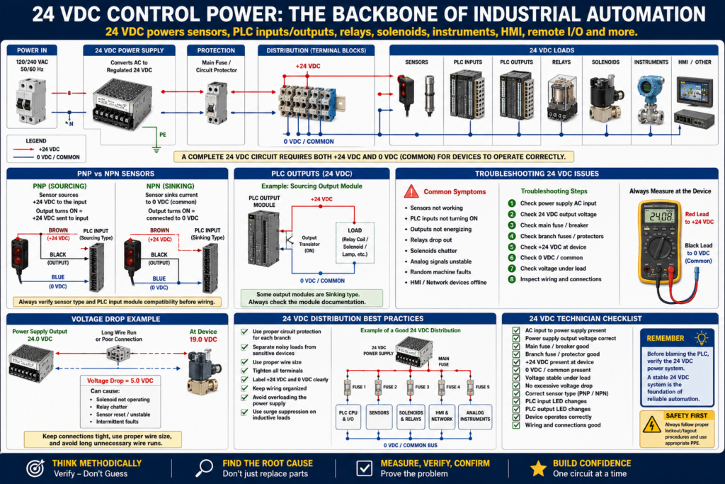
In modern industrial automation, 24 VDC control power is one of the most important systems inside a machine.
Many devices depend on it:
PLC inputs
PLC outputs
Photoelectric sensors
Proximity sensors
Limit switches
Solenoid valves
Relays
Analog transmitters
HMI control circuits
Remote I/O modules
Network switches
Safety devices
When 24 VDC control power is healthy, the machine can read sensors, energize outputs, communicate with field devices, and execute logic correctly.
When 24 VDC control power has problems, the machine can behave in strange ways:
PLC inputs flicker
Sensors turn off randomly
Solenoids chatter
Relays drop out
Analog signals become unstable
Remote I/O loses communication
HMI alarms appear
Machine faults intermittently
That is why every automation technician must understand how 24 VDC control power works and how to troubleshoot it.
1. What Is 24 VDC Control Power?
24 VDC control power is a low-voltage DC power system commonly used to operate control devices in industrial equipment.
A typical 24 VDC circuit has two main conductors:
+24 VDC
0 VDC / Common
The +24 VDC side provides the positive voltage.
The 0 VDC/common side provides the return path.
For a device to work, it usually needs both.
+24 VDC → Device → 0 VDC/CommonA common mistake is checking only the positive side and assuming the circuit is good.
But voltage alone is not enough.
The circuit must have a complete path.
2. Why 24 VDC Is So Common
24 VDC is widely used in automation because it is:
| Reason | Explanation |
|---|---|
| Safer than higher control voltages | Lower shock hazard compared to 120 VAC or 240 VAC control circuits |
| PLC friendly | Most modern PLC input and output cards are designed for 24 VDC |
| Sensor friendly | Most industrial sensors operate on 10–30 VDC or 24 VDC nominal |
| Reliable | Good for digital signals, relays, valves, and instruments |
| Easier to troubleshoot | Simple polarity and common reference |
| Compatible with instrumentation | Many transmitters and analog devices use 24 VDC loop power |
In older panels, you may still see 120 VAC control circuits.
But in many modern machines, 24 VDC is the standard for control.
3. Basic 24 VDC Power Supply Circuit
A control panel usually has an AC power source feeding a DC power supply.
Example:
120 VAC or 240 VAC Input
        ↓
24 VDC Power Supply
        ↓
+24 VDC and 0 VDC/Common
        ↓
Control devices
A simple 24 VDC distribution path may look like this:
24 VDC Power Supply
        ↓
Fuse or circuit protection
        ↓
Terminal blocks
        ↓
Sensors / PLC inputs / relays / solenoids
        ↓
0 VDC common return
The power supply converts AC voltage into regulated DC voltage.
4. The Importance of 0 VDC / Common
The common is just as important as the positive side.
Many technicians focus only on +24 VDC and forget the return path.
But every circuit needs a complete loop.
Example:
+24 VDC → Sensor electronics → 0 VDC/CommonIf the common is missing, loose, broken, or connected to the wrong reference, the device may not operate correctly.
Common-related problems
Sensor has power on brown wire but does not turn on.
PLC input does not change even when sensor LED is ON.
Analog signal is unstable.
Relay coil does not energize.
Remote I/O module faults.
Multiple sensors behave strangely.
When several devices act weird at the same time, always suspect a common or power distribution problem.
5. 24 VDC and PLC Inputs
PLC inputs are used to read field signals.
A sensor, switch, or contact sends a signal to the PLC input module.
Basic example:
Photoeye detects product
        ↓
Sensor output turns ON
        ↓
PLC input receives signal
        ↓
PLC input LED turns ON
        ↓
PLC logic sees input as TRUE
A typical 3-wire DC sensor uses:
Brown  = +24 VDC
Blue   = 0 VDC/Common
Black  = Signal output
When the sensor detects the target, the black wire changes state and sends a signal to the PLC input.
6. PNP and NPN Sensors
In 24 VDC systems, you will often see PNP and NPN sensors.
This is very important.
PNP Sensor
A PNP sensor switches positive voltage to the PLC input.
PNP = switches +24 VDC to the inputBasic idea:
Sensor ON → PLC input receives +24 VDCPNP is often called sourcing because it sources positive voltage to the load/input.
NPN Sensor
An NPN sensor switches the input to 0 VDC/common.
NPN = switches common/0 VDC to the inputBasic idea:
Sensor ON → PLC input is connected to 0 VDCNPN is often called sinking because it sinks current to common.
Why this matters
If the PLC input card is not compatible with the sensor type, the input may never turn on.
Example:
PNP sensor connected to an input module wired for NPN logic = possible no input signalAlways verify:
Sensor type
PLC input module type
Wiring diagram
Common connection
Signal polarity
7. 24 VDC and PLC Outputs
PLC outputs control devices.
Common 24 VDC output loads include:
Relay coils
Solenoid valves
Stack lights
Buzzers
Small contactor coils
Interposing relays
Pilot lights
Basic example:
PLC logic turns output ON
        ↓
PLC output module energizes
        ↓
Relay coil or solenoid receives 24 VDC
        ↓
Field device operates
However, the PLC output does not always directly power the final load.
Sometimes the PLC output energizes an interposing relay, and the relay controls another device.
Example:
PLC Output → Interposing Relay → Contactor Coil → Motor StarterThis protects the PLC output and allows isolation between circuits.
8. Fusing and Circuit Protection
24 VDC circuits should be protected.
Protection may include:
Main 24 VDC fuse
Branch fuses
Electronic circuit protectors
Individual fused terminal blocks
Power supply protection
Good circuit protection helps isolate faults.
Instead of one short circuit killing the entire 24 VDC system, a properly protected branch circuit can trip only the affected section.
Example:
Power Supply
   ↓
Main Fuse
   ↓
Branch Fuse 1 → PLC Inputs
Branch Fuse 2 → Sensors
Branch Fuse 3 → Solenoids
Branch Fuse 4 → Network Switch
This makes troubleshooting easier.
9. Voltage Drop in 24 VDC Circuits
Voltage drop is a common problem in low-voltage control circuits.
Because the voltage is only 24 VDC, losing a few volts can matter.
Example:
Power supply output = 24.0 VDC
Voltage at solenoid = 19.0 VDC
Voltage drop = 5.0 VDC
That may cause:
Solenoid does not shift
Relay chatters
Sensor resets
Input flickers
Valve operates intermittently
Common causes of voltage drop:
Loose terminals
Long cable runs
Undersized wire
Corroded connections
Bad relay contacts
Overloaded power supply
Damaged cable
Bad terminal block
Always measure voltage at the device, not only at the power supply.
10. Measuring 24 VDC Correctly
When troubleshooting, use a multimeter carefully and logically.
Check power supply output
Measure:
Red lead → +24 VDC terminal
Black lead → 0 VDC/Common terminal
Expected:
Approximately 24 VDCMost systems may read around:
23.5 to 24.5 VDCSome systems may be adjusted slightly higher, for example:
24.5 VDCdepending on the design.
Check voltage at the field device
Do not only measure at the power supply.
Measure at the device terminals:
Sensor brown to blue
Solenoid positive to common
Relay coil A1 to A2
Remote I/O power terminals
This confirms the device is actually receiving power.
Check voltage under load
A circuit may show good voltage when the load is OFF but drop when the load turns ON.
Example:
Solenoid OFF = 24 VDC present
Solenoid ON = voltage drops to 18 VDC
This usually indicates:
Weak power supply
High-resistance connection
Undersized wiring
Overloaded circuit
Bad terminal
11. Common 24 VDC Troubleshooting Symptoms
Symptom 1 — No sensors have power
Possible causes:
24 VDC power supply off
Blown main fuse
Tripped circuit protector
No AC input to power supply
Bad power supply
Disconnected common
Symptom 2 — One sensor does not work
Possible causes:
Bad sensor
Sensor misaligned
Broken cable
Loose terminal
Blown branch fuse
Wrong sensor type
No +24 VDC
No 0 VDC/common
Symptom 3 — PLC input LED turns ON, but logic does not respond
Possible causes:
Wrong input address/tag
Input buffering issue
Faulted input module
Forces active
Wrong PLC routine not being scanned
XIC/XIO logic misunderstanding
Symptom 4 — Output LED turns ON, but device does not energize
Possible causes:
No output field power
Blown output fuse
Bad output module
Bad relay coil
Bad solenoid coil
Missing common
Broken wire
Device mechanically stuck
Symptom 5 — Several devices flicker or reset
Possible causes:
Power supply overloaded
Loose common
Bad 0 VDC terminal
Short circuit intermittently loading supply
Electrical noise
Bad grounding/bonding
Poor wire termination
12. 24 VDC and Analog Instruments
Many industrial instruments use 24 VDC power.
Examples:
Pressure transmitters
Level transmitters
Flow transmitters
Temperature transmitters
Conductivity transmitters
pH transmitters
A common signal is:
4–20 mAIn many cases, the same 24 VDC system powers the transmitter loop.
Basic concept:
24 VDC supply powers transmitter
Transmitter sends 4–20 mA signal to analog input card
PLC scales signal into engineering units
Example:
4 mA  = 0 PSI
20 mA = 100 PSI
Stable 24 VDC is important for stable analog readings.
Poor power or grounding can create noisy analog signals.
13. 24 VDC Distribution Best Practices
A professional control panel should have organized 24 VDC distribution.
Good practices include:
Separate branch protection for different device groups.
Label +24 VDC and 0 VDC terminals clearly.
Separate noisy loads from sensitive analog devices when possible.
Use proper wire size.
Tighten terminals correctly.
Use ferrules where appropriate.
Document power distribution on drawings.
Avoid overloading the power supply.
Use surge suppression on inductive loads.
Keep wiring organized.
For example, avoid putting everything on one unprotected 24 VDC branch.
Better design:
Branch 1 = PLC CPU and I/O
Branch 2 = Sensors
Branch 3 = Solenoids and relays
Branch 4 = HMI/network devices
Branch 5 = Analog instruments
This makes faults easier to isolate.
14. Real-World Troubleshooting Example
Problem
A machine suddenly has multiple sensor faults.
Several photoeyes are not turning ON, and the PLC shows missing inputs.
Step 1 — Check 24 VDC power supply
Measure power supply output:
+24 VDC to 0 VDC = 24.1 VDCPower supply looks good.
Step 2 — Check sensor power at field device
Measure at one photoeye:
Brown to blue = 0 VDCThe sensor is not receiving power.
Step 3 — Check branch fuse
The branch fuse feeding the sensor group is blown.
Replace fuse?
Not yet.
First ask:
Why did the fuse blow?Step 4 — Inspect sensor cables
A cable near a conveyor is damaged and shorted to the frame.
Step 5 — Correct the root cause
Repair or replace the damaged cable.
Then replace the fuse.
Step 6 — Verify operation
Confirm:
24 VDC present at sensors
Sensor LEDs operate correctly
PLC input LEDs turn ON
PLC tags change online
Machine faults reset
Root cause:
Damaged sensor cable caused 24 VDC branch fuse to blow.This is professional troubleshooting.
15. Technician Checklist for 24 VDC Problems
Use this checklist when troubleshooting 24 VDC control issues:
Is AC input power present at the power supply?
Is the 24 VDC power supply ON?
Is the output voltage correct?
Is the main 24 VDC fuse good?
Are branch fuses or circuit protectors tripped?
Is +24 VDC present at the device?
Is 0 VDC/common present at the device?
Is voltage stable under load?
Is there voltage drop?
Are terminals tight?
Are cables damaged?
Is the sensor type correct?
Is the PLC input LED changing?
Is the PLC output LED changing?
Is the device mechanically free to operate?
Are multiple devices affected or only one?
Common Mistakes
Mistake 1 — Measuring only at the power supply
The power supply may be good, but the device may not receive voltage.
Always check at the load.
Mistake 2 — Forgetting the common
A missing common can stop a circuit just like a missing positive wire.
Mistake 3 — Replacing a blown fuse without finding the cause
A fuse opens for a reason. Find the short, overload, or failed device.
Mistake 4 — Ignoring voltage drop
A device may receive some voltage, but not enough voltage to work correctly.
Mistake 5 — Mixing PNP and NPN without checking compatibility
The sensor and PLC input must match the wiring design.
Mistake 6 — Connecting too many loads to one power supply
An overloaded supply can create random, hard-to-find faults.
Final Thoughts
24 VDC control power is the backbone of modern industrial automation.
It powers the sensors that tell the PLC what is happening.
It powers the outputs that control relays, solenoids, and indicators.
It powers instruments, remote I/O, network switches, and many control devices.
When 24 VDC is stable, the control system can operate reliably.
When 24 VDC is unstable, missing, overloaded, or poorly distributed, the machine can become unpredictable.
A strong automation technician knows how to follow the 24 VDC path:
Power Supply → Protection → Terminal Blocks → Field Device → PLC Input/Output → Common ReturnThe key is to troubleshoot logically.
Do not guess.
Do not replace parts blindly.
Measure the voltage.
Check the common.
Verify the fuse.
Check the device.
Confirm the PLC input or output.
Find the root cause.
In automation troubleshooting, 24 VDC is one of the first things you should verify and one of the last things you should ignore.