6. VFD Basics for Automation Technicians
VFD Basics: What a Variable Frequency Drive Does and Why It Matters
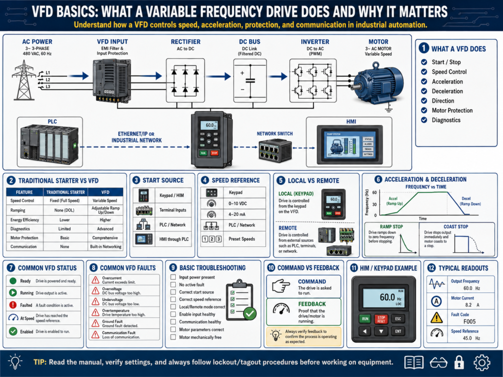
A VFD, or Variable Frequency Drive, is one of the most common motor control devices used in modern industrial automation.
A traditional motor starter mainly turns a motor ON or OFF.
A VFD does much more.
It can control:
Motor start
Motor stop
Motor speed
Acceleration time
Deceleration time
Direction
Motor protection
Fault detection
Status feedback
Communication with PLCs and HMIs
This makes the VFD one of the most important devices for an automation technician to understand.
You will see VFDs controlling conveyors, pumps, fans, mixers, agitators, fillers, blowers, compressors, and many other industrial machines.
1. What Is a VFD?
A VFD is an electronic motor controller that controls the speed and torque of an AC motor by changing the frequency and voltage sent to the motor.
Basic idea:
VFD changes frequency → Motor speed changesIn many industrial plants, a standard AC induction motor is designed to run at a fixed speed when connected directly to line power.
For example:
60 Hz power → Motor runs near full rated speed
30 Hz output → Motor runs around half speed
The VFD allows the motor to run slower, faster within limits, ramp smoothly, stop smoothly, and provide diagnostic information.
2. Traditional Starter vs VFD
| Feature | Motor Starter | VFD |
|---|---|---|
| Starts motor | Yes | Yes |
| Stops motor | Yes | Yes |
| Controls speed | No | Yes |
| Acceleration ramp | No | Yes |
| Deceleration ramp | No | Yes |
| Motor protection | Basic overload | Advanced protection |
| Direction control | Requires reversing starter | Usually parameter controlled |
| PLC communication | Limited | Often available |
| Fault diagnostics | Basic | Detailed fault codes |
| Energy savings | Limited | Possible with variable speed loads |
A motor starter is simple and reliable.
A VFD is more advanced and gives better control.
3. Why VFDs Are Used
VFDs are used because they provide better control over motor operation.
Common reasons:
Speed control
Soft starting
Reduced mechanical shock
Energy savings
Better process control
Reduced wear on belts, chains, gearboxes, and couplings
Motor protection
PLC and HMI diagnostics
Example:
A conveyor does not always need to run at full speed.
A pump may need to adjust flow.
A fan may need to adjust airflow.
A mixer may need different speeds for different products.
A VFD allows the control system to adjust the motor instead of simply turning it ON or OFF.
4. Basic VFD Power Flow
A basic VFD power path looks like this:
Incoming AC Power
        ↓
VFD Input
        ↓
Rectifier Section
        ↓
DC Bus
        ↓
Inverter Section
        ↓
Variable Frequency Output
        ↓
Motor
The VFD takes fixed-frequency AC power and converts it into a controlled output for the motor.
Simplified:
Fixed AC in → Controlled AC outThe input side may be 240 VAC or 480 VAC.
The output side goes to the motor and changes frequency depending on the speed command.
5. Frequency and Motor Speed
Frequency is one of the most important VFD concepts.
In the United States, standard AC power is commonly:
60 HzA motor connected directly to 60 Hz power runs near its rated base speed.
When a VFD lowers the frequency, the motor runs slower.
Example:
60 Hz = full speed
30 Hz = approximately half speed
15 Hz = approximately quarter speed
This is simplified because actual speed depends on motor design, slip, load, and control method, but the basic relationship is very useful.
6. Start Source
The start source tells the VFD where the start command comes from.
Common start sources:
Keypad / HIM
Digital input terminals
PLC over network
Hardwired push button
Remote I/O
HMI through PLC
Example:
If the drive is configured for terminal control, pressing Start on the keypad may not start the motor.
If the drive is configured for network control, the PLC may need to send the start command.
This is one of the first things to check when a VFD does not start.
Technician question
Ask:
Where is the drive expecting the Start command from?7. Speed Reference
The speed reference tells the VFD what speed to run.
Common speed references:
Keypad / HIM speed setting
Analog input 0–10 VDC
Analog input 4–20 mA
PLC command over network
Preset speeds
Potentiometer
HMI speed setpoint through PLC
Example:
The VFD may receive a Start command but still not run because the speed reference is zero.
Technician question
Ask:
Where is the drive expecting the speed command from?
Is the speed reference greater than zero?
8. Acceleration and Deceleration
A VFD does not have to start or stop the motor instantly.
It can ramp the motor speed up and down.
Acceleration
Acceleration is the time it takes the motor to ramp from zero speed to the commanded speed.
Example:
Acceleration Time = 5 secondsThe motor ramps smoothly instead of starting suddenly.
Deceleration
Deceleration is the time it takes the motor to ramp down from running speed to zero.
Example:
Deceleration Time = 5 secondsIf the decel time is too short, the drive may fault because the motor and load cannot slow down that quickly.
Common fault:
DC Bus OvervoltageThis can happen when the motor acts like a generator during deceleration.
9. Coast Stop vs Ramp Stop
VFDs can stop motors in different ways.
Coast Stop
The VFD removes output power and the motor spins down naturally.
Drive output OFF → Motor coasts to stopThis is like removing power from a motor.
Ramp Stop
The VFD controls the motor down to zero speed based on the deceleration time.
Drive reduces frequency gradually → Motor slows under controlRamp stop gives better control, but if the decel time is too aggressive, the drive may fault.
10. VFD Inputs and Outputs
A VFD may have many control terminals.
Common digital inputs:
Start
Stop
Forward
Reverse
Reset fault
Preset speed select
Enable
Jog
Common analog inputs:
0–10 VDC speed reference
4–20 mA speed reference
Common relay outputs or digital outputs:
Drive running
Drive faulted
At speed
Ready
Alarm
These signals allow the VFD to interact with the PLC and control system.
11. VFD Communication with PLC
Modern VFDs often communicate with PLCs over industrial networks.
Examples:
EtherNet/IP
Profinet
Modbus TCP
DeviceNet
ControlNet
Profibus
Through communication, a PLC may read:
Drive status
Running feedback
Fault code
Output frequency
Motor current
Motor voltage
Speed feedback
Ready status
And the PLC may write:
Start command
Stop command
Speed reference
Direction command
Fault reset
This is powerful because the HMI can display detailed drive information.
Example:
HMI shows:
Drive Faulted
Fault Code 12
Output Frequency 45 Hz
Motor Current 3.2 A
Speed Reference 75%
12. Important VFD Status Signals
Automation technicians should understand common drive status signals.
| Status | Meaning |
|---|---|
| Ready | Drive is healthy and ready to run |
| Running | Drive is actively outputting power to motor |
| Faulted | Drive has a fault and may be stopped |
| At Speed | Drive reached commanded speed |
| Enabled | Drive is allowed to run |
| Direction | Forward or reverse operation |
| Local Mode | Drive controlled from keypad/HIM |
| Remote Mode | Drive controlled from terminals or network |
A drive may have power and still not be ready to run.
Always check drive status.
13. Common VFD Faults
Common VFD faults include:
Overcurrent
Overvoltage
Undervoltage
Ground fault
Motor overload
Drive overload
Input phase loss
Output phase loss
Overtemperature
Communication fault
External fault
Encoder feedback fault
Safe torque off active
A fault code is not the final answer.
It is a clue.
Example:
Overcurrent faultPossible causes:
Motor short
Motor cable problem
Mechanical jam
Acceleration time too short
Wrong motor parameters
Bad drive
Ground fault
Load problem
Professional troubleshooting means using the fault code, machine condition, motor current, wiring, and mechanical inspection together.
14. VFD Motor Nameplate Parameters
A VFD should be programmed with correct motor data.
Important motor nameplate values:
Motor voltage
Full load amps
Frequency
RPM
Horsepower
Service factor
Power factor
Motor type
Incorrect motor data can cause poor performance, nuisance faults, or motor overheating.
When replacing a VFD, always compare the motor nameplate with the drive parameters.
15. Auto-Tune
Many drives have an auto-tune function.
Auto-tune helps the VFD learn motor characteristics.
Depending on the drive, auto-tune may be:
Static auto-tune
Rotating auto-tune
Static auto-tune
The motor does not rotate, or movement is limited.
Used when the load cannot safely rotate.
Rotating auto-tune
The motor rotates during the test.
This can provide better motor data, but it must be done safely.
Important:
Lockout/tagout requirements
Machine safety
Load condition
Motor uncoupled or coupled
Manufacturer procedure
Never run auto-tune without understanding what will move.
16. Basic VFD Troubleshooting: Drive Does Not Start
Problem:
Drive powers up, but motor does not run.Check:
Is the drive faulted?
Is the drive in local or remote mode?
Is the start source correct?
Is the speed reference correct?
Is the speed reference above zero?
Is the stop input active?
Is enable input present?
Is Safe Torque Off active?
Is PLC sending command?
Is communication healthy?
Is motor connected?
Is motor overload active?
Is the drive ready?
Do not only check one thing.
Follow the command path.
17. Basic VFD Troubleshooting: Drive Starts but Motor Does Not Turn
Possible causes:
Speed reference is zero
Output frequency is zero
Motor disconnected
Output contactor open
Safe Torque Off active
Wrong parameters
Motor brake not releasing
Mechanical jam
Motor failed
Drive output problem
Useful checks:
Check output frequency
Check motor current
Check output voltage
Check motor leads
Check mechanical load
Check brake circuit if installed
18. Basic VFD Troubleshooting: Drive Faults on Start
Possible causes:
Mechanical jam
Acceleration too fast
Motor short
Motor cable fault
Ground fault
Incorrect motor parameters
Bad motor
Load too heavy
Output wiring issue
Useful checks:
Read the exact fault code.
Check when the fault occurs.
Check motor current.
Inspect motor cable.
Megger motor only if safe and allowed by procedure.
Check mechanical load.
Verify motor parameters.
Review acceleration time.
19. Basic VFD Troubleshooting: Overvoltage on Stop
If a VFD faults during stopping, especially during fast deceleration, it may be a DC bus overvoltage issue.
Common causes:
Deceleration time too short
High-inertia load
No braking resistor
Braking resistor failed
Regeneration from the motor
Incorrect stop mode
Possible corrections may include:
Increase deceleration time
Use coast stop if acceptable
Check braking resistor
Check braking transistor
Review load inertia
Always follow plant standards and manufacturer procedures.
20. Technician Checklist for VFD Issues
Use this checklist when troubleshooting a VFD:
Drive has input power
Drive display/HIM is active
No active fault
Drive is in correct control mode
Start source is correct
Speed reference source is correct
Speed reference is above zero
Enable input is active
Stop input is healthy
Safe Torque Off is not active
PLC communication is healthy
Motor parameters are correct
Motor overload setting is correct
Acceleration/deceleration times are reasonable
Motor cable is healthy
Motor is mechanically free
Output frequency is present when running
Motor current is normal
Fault code is documented
21. Common Mistakes New Technicians Make
Mistake 1 — Looking only at the fault code
The fault code is a clue, not the root cause.
Mistake 2 — Not checking start source
The drive may be waiting for a command from terminals, network, or keypad.
Mistake 3 — Not checking speed reference
A VFD can be commanded to run with a speed reference of zero.
Mistake 4 — Ignoring local/remote mode
A drive in local mode may ignore PLC commands.
A drive in remote mode may ignore keypad commands.
Mistake 5 — Replacing the VFD too quickly
Many VFD problems are caused by wiring, parameters, motor issues, mechanical load, or communication problems.
Mistake 6 — Not backing up parameters
Before replacing or modifying a VFD, save the parameters if possible.
Final Thoughts
A VFD is much more than an electronic motor starter.
It controls motor speed, ramping, direction, protection, diagnostics, and communication.
For an automation technician, understanding VFDs is critical because many industrial machines depend on them.
A strong technician understands:
Start source
Speed reference
Local/remote mode
Acceleration
Deceleration
Fault codes
Motor parameters
PLC communication
Command vs feedback
Drive status
When a VFD problem occurs, do not guess.
Check the drive status.
Read the exact fault code.
Verify the start source.
Verify the speed reference.
Check local/remote mode.
Confirm the PLC command.
Check motor current.
Inspect the motor and load.
Find the root cause.
A VFD does not just start a motor. It controls how the motor behaves.
Understanding that difference is a major step in becoming a stronger automation technician.