7. Motor Feedback, Faults, and Interlocks (7 of 41)
Motor Feedback, Faults, and Interlocks: Command vs Proof in Industrial Automation
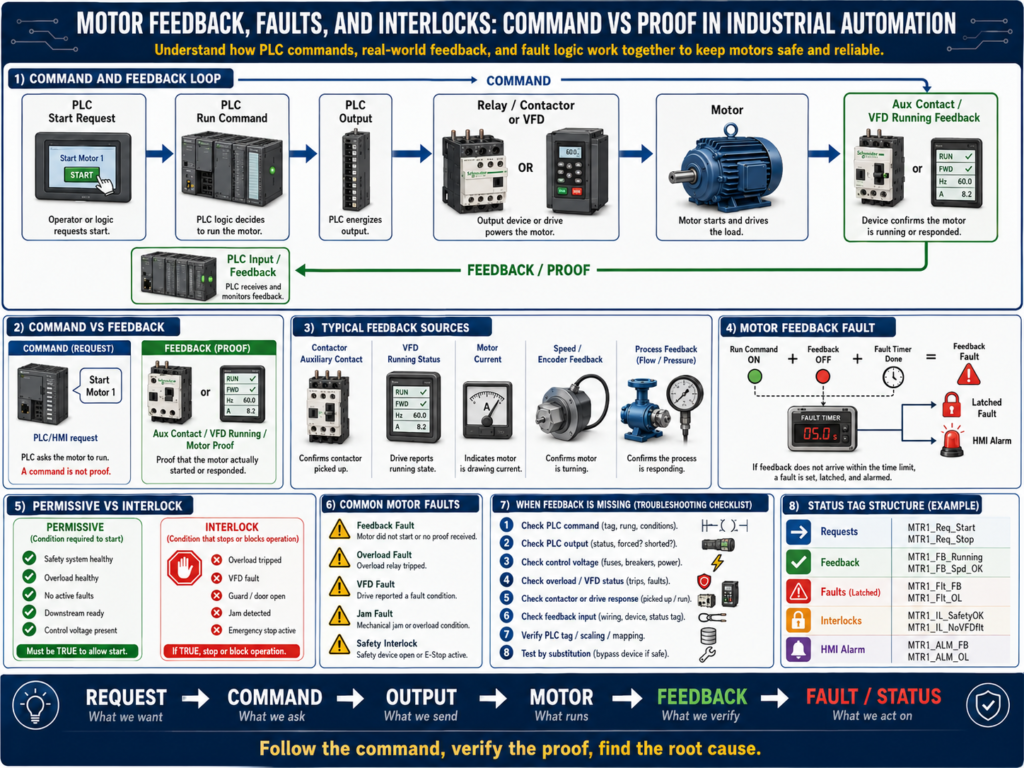
One of the most important concepts in industrial automation is this:
A command is not the same as proof.
A PLC can command a motor to run, but that does not guarantee the motor actually started.
A motor may fail to run because of:
Blown fuse
Tripped overload
Bad contactor coil
Bad relay
Broken wire
Open safety circuit
VFD fault
Missing enable signal
Mechanical jam
Bad feedback contact
Communication fault
That is why professional PLC programs use feedback, faults, and interlocks.
These are the tools that allow the control system to know whether the real machine is doing what the logic expected.
1. Command vs Feedback
Command
A command is the request from the control system.
Examples:
PLC output ON
Motor_Start_Command = TRUE
VFD Run Command = TRUE
Conveyor_Run_Cmd = TRUE
Pump_Start_Cmd = TRUE
The command means:
The PLC wants the motor to run.But it does not prove the motor is running.
Feedback
Feedback is proof from the real system.
Examples:
Contactor auxiliary contact closed
VFD running status ON
Motor current detected
Zero-speed switch changed state
Encoder speed greater than zero
Pressure increased after pump started
Flow switch active
Feedback means:
The motor or process responded to the command.A professional technician always separates the two.
2. Simple Example
A PLC turns ON a motor output.
PLC Output ON
     ↓
Relay energizes
     ↓
Contactor coil energizes
     ↓
Contactor power contacts close
     ↓
Motor receives power
     ↓
Auxiliary contact closes
     ↓
PLC receives motor feedback
The PLC output is the command.
The auxiliary contact is the feedback.
Command = PLC is asking the motor to run
Feedback = proof that the contactor pulled in
3. Why Feedback Matters
Without feedback, the PLC may believe the motor is running even when it is not.
Example:
PLC Output = ON
Motor physically = OFF
This can create major problems:
Conveyor sequence fails
Pump does not move product
Mixer does not rotate
Filler does not fill correctly
Downstream equipment waits forever
Machine timing becomes incorrect
Safety or quality issue occurs
Operator gets poor diagnostic information
Feedback allows the PLC to detect a failure and generate a fault.
4. Types of Motor Feedback
Motor feedback can come from different sources depending on the system.
Contactor Auxiliary Feedback
A normally open auxiliary contact closes when the contactor pulls in.
Contactor pulled in → Aux contact closes → PLC input ONThis proves the contactor changed state.
It does not always prove the motor shaft is rotating, but it confirms the starter responded.
VFD Running Feedback
A VFD can provide a running status through:
Hardwired relay output
Digital output
EtherNet/IP status bit
DeviceNet status bit
Modbus register
Profinet status bit
This feedback tells the PLC that the drive is running or outputting to the motor.
Motor Current Feedback
Some systems confirm motor operation by checking current.
Example:
Motor command ON
AND motor current greater than minimum threshold
= motor confirmed running
This is useful when the system needs proof that current is being drawn.
Speed Feedback
Speed feedback may come from:
Encoder
Tachometer
VFD speed feedback
Zero-speed switch
Proximity sensor on shaft
This is stronger feedback because it proves motion.
Process Feedback
Sometimes the best proof is from the process.
Examples:
Pump starts → flow switch turns ON
Pump starts → pressure increases
Conveyor starts → encoder pulses detected
Fan starts → airflow switch proves flow
Mixer starts → motor current rises
This confirms that the equipment is producing the expected process result.
5. What Is a Motor Feedback Fault?
A motor feedback fault happens when the PLC commands a motor to run, but feedback does not appear within a certain time.
Example:
Motor command turns ON
Timer starts
Feedback must turn ON within 3 seconds
If feedback does not turn ON → Motor Feedback Fault
Simple logic concept:
Motor_Run_Command = ON
AND Motor_Feedback = OFF
AND Timer Done = TRUE
THEN Motor_Feedback_Fault = TRUE
This prevents the PLC from assuming the machine is running correctly.
6. Feedback Fault Example
Condition
PLC commands conveyor motor to run.Expected response
Contactor pulls in.
Auxiliary feedback turns ON.
Fault condition
After 3 seconds, auxiliary feedback is still OFF.PLC action
Latch Conveyor_Motor_Feedback_Fault.
Stop conveyor command.
Display alarm on HMI.
Require operator or technician reset after issue is corrected.
This gives the operator a clear message instead of just “machine stopped.”
7. Feedback Fault Causes
If a motor feedback fault occurs, possible causes include:
PLC output did not turn ON
Output fuse blown
Interposing relay failed
Contactor coil failed
No control voltage at coil
Overload tripped
Safety circuit open
Bad auxiliary contact
Broken feedback wire
Bad PLC input
Incorrect feedback logic
VFD not ready
VFD faulted
Motor starter failed
This is why the technician must follow the path logically.
Do not immediately replace the motor.
8. Feedback Fault Troubleshooting Path
When a motor feedback fault occurs, check:
1. Is the motor command ON in the PLC?
2. Is the PLC output ON?
3. Is voltage present at the output terminal?
4. Is the interposing relay energizing?
5. Is voltage reaching the contactor coil or VFD run input?
6. Is the overload healthy?
7. Is the safety circuit healthy?
8. Does the contactor pull in or does the VFD run?
9. Does the auxiliary feedback or VFD running bit turn ON?
10. Does the PLC input see the feedback?
11. Is the PLC logic using the correct feedback bit?
A professional technician follows the chain from command to proof.
9. What Is an Interlock?
An interlock is a condition that stops or blocks equipment when operation is not allowed.
Examples:
Guard door open
E-stop active
Overload tripped
VFD faulted
Downstream conveyor stopped
Jam sensor active
Tank level too low
Pressure too high
Air pressure low
Motor feedback fault active
An interlock protects the machine, the process, or the operator.
Simple concept:
If unsafe or invalid condition exists → stop or block operation10. Interlock vs Permissive
This is a very important distinction.
Permissive
A permissive allows equipment to start.
Example:
Motor can start only if:
- Safety healthy
- Overload healthy
- No active fault
- Auto mode selected
- Downstream ready
Interlock
An interlock removes or blocks operation while running.
Example:
Stop motor if:
- Guard door opens
- Overload trips
- VFD faults
- Jam sensor activates
- Downstream conveyor stops
A simple way to think about it:
Permissive = permission to start
Interlock = reason to stop or block
In many systems, the same condition may be used in both places.
For example, overload healthy may be a permissive to start and overload tripped may be an interlock while running.
11. Motor Faults vs Motor Alarms
Motor Fault
A fault usually stops or prevents operation.
Examples:
Motor feedback fault
Overload fault
VFD fault
Starter failure
Motor overcurrent
Motor thermal overload
Faults often require a reset after the condition clears.
Motor Alarm
An alarm informs the operator about a condition.
Examples:
Motor runtime high
Motor current warning
VFD warning active
Motor maintenance due
Bearing temperature high warning
An alarm may not always stop the motor immediately.
Simple difference:
Fault = stops or prevents operation
Alarm = informs operator or maintenance
12. Latched Faults
Many motor faults should be latched.
A latched fault stays active until the problem is corrected and reset.
Example:
Motor feedback missing
     ↓
Feedback fault latches
     ↓
Motor command disabled
     ↓
Operator sees fault on HMI
     ↓
Technician fixes issue
     ↓
Reset button clears fault
Why latch faults?
Because some problems are intermittent.
Without a latch, the fault may disappear before the technician can see what happened.
13. Fault Reset Logic
A good reset should not blindly clear all faults.
The fault condition should be corrected first.
Example:
Reset allowed only when:
- Reset button pressed
- Fault condition is no longer active
- Safety is healthy
- Motor command is OFF
Basic concept:
Reset PB
AND Fault Condition Cleared
THEN Unlatch Fault
Avoid reset logic that clears faults while the actual problem is still present.
14. VFD Feedback and Faults
With a VFD, feedback can be more advanced.
The PLC may monitor:
Drive Ready
Drive Running
Drive Faulted
Drive Warning
At Speed
Output Frequency
Motor Current
Fault Code
Communication Healthy
Example logic:
PLC sends VFD Run Command
AND VFD Running Feedback does not turn ON within 3 seconds
= VFD Run Feedback Fault
Another example:
VFD Faulted Status = ON
= Motor Drive Fault
If the VFD is on Ethernet/IP, the HMI may display a specific fault code instead of a generic motor fault.
15. Command, Feedback, and Fault Example
Example motor system:
Conveyor 1 MotorCommand bits
Conv1_Start_Request
Conv1_Run_Command
Conv1_Stop_Command
Feedback bits
Conv1_Running_Feedback
Conv1_VFD_Ready
Conv1_VFD_Running
Conv1_At_Speed
Fault bits
Conv1_Feedback_Fault
Conv1_Overload_Fault
Conv1_VFD_Fault
Conv1_Jam_Fault
Interlock bits
Conv1_Safety_Interlock
Conv1_Downstream_Interlock
Conv1_Jam_Interlock
Conv1_Fault_Interlock
This structure makes troubleshooting much easier.
16. Basic PLC Logic Structure
A clean motor logic structure may look like this:
1. Input Buffering
2. Requests
3. Permissives
4. Interlocks
5. Command Logic
6. Feedback Monitoring
7. Fault Logic
8. Output Logic
9. HMI Status
This separates the logic into readable sections.
Example:
Start Request + Permissives OK + No Interlocks = Run Command
Run Command + No Feedback after delay = Feedback Fault
Feedback Fault = Stop Command + HMI Alarm
This is much cleaner than mixing everything into one large rung.
17. Technician Troubleshooting Example
Problem
HMI shows:
Conveyor Motor Feedback FaultStep 1 — Check PLC command
Is the PLC commanding the motor?
Conv1_Run_Command = ON?If no, the motor is not being asked to run. Check permissives, interlocks, mode, or requests.
Step 2 — Check PLC output
Is the output ON?
Conv1_Motor_Output = ON?If no, check logic.
If yes, continue.
Step 3 — Check control voltage
Measure at relay or contactor coil.
A1 to A2 = correct control voltage?If no, trace control circuit.
Step 4 — Check overload or VFD
Is the overload tripped?
Is the VFD faulted?
Is the drive ready?
Step 5 — Check feedback signal
If the contactor pulls in but feedback is missing, check:
Auxiliary contact
Feedback wire
PLC input LED
Input module common
PLC input tag
Step 6 — Find root cause
Possible root cause:
Bad auxiliary contact on contactor.Corrective action:
Replace or repair auxiliary contact.
Verify feedback input.
Reset fault.
Test motor start.
Document issue.
18. Common Mistakes New Technicians Make
Mistake 1 — Thinking command means running
A PLC output ON does not prove the motor is running.
Always check feedback.
Mistake 2 — Resetting faults without checking cause
If the fault returns, the root cause was never fixed.
Mistake 3 — Ignoring feedback wiring
Sometimes the motor runs fine, but the PLC does not see the feedback.
That is still a control problem.
Mistake 4 — Confusing permissives and interlocks
Permissives allow starting.
Interlocks stop or block operation.
Keeping them separate makes troubleshooting easier.
Mistake 5 — Not checking the VFD status
A drive may be powered but not ready, faulted, disabled, in local mode, or missing speed reference.
19. Technician Checklist
When troubleshooting motor command and feedback problems, verify:
Motor start request exists
All permissives are true
No interlocks are active
No fault is latched
PLC run command is ON
PLC output is ON
Output fuse is good
Relay or contactor coil receives voltage
Overload is healthy
VFD is ready
VFD is not faulted
Contactor pulls in
Motor receives power
Motor runs mechanically
Feedback device changes state
PLC input LED turns ON
PLC feedback tag changes online
Feedback timer setting is reasonable
Fault reset condition is correct
Final Thoughts
Motor feedback, faults, and interlocks are what make motor control reliable and professional.
A simple motor command is not enough.
The PLC must know:
Was the motor commanded?
Did the starter or VFD respond?
Did feedback turn ON?
Did a fault occur?
Should the motor be stopped?
Can the operator reset the fault?
This is the difference between basic control and professional automation logic.
A strong automation technician understands the full chain:
Request → Command → Output → Starter/VFD → Motor → Feedback → Fault/StatusWhen troubleshooting, do not guess.
Follow the command.
Verify the output.
Check the control circuit.
Check the starter or VFD.
Confirm the feedback.
Find the root cause.
In industrial automation, a command is only a request. Feedback is the proof.