10. Grounding and Bonding in Control Panels (10 of 41)
Grounding and bonding are two of the most important concepts in industrial electrical systems.
They affect:
Electrical safety
Fault clearing
Noise reduction
VFD performance
Analog signal stability
Communication reliability
PLC input stability
Sensor reliability
Panel protection
Many technicians hear the words grounding and bonding together, but they are not exactly the same thing.
Understanding the difference helps you troubleshoot panels, motors, VFDs, sensors, instruments, and communication issues more professionally.
A machine can have perfect PLC logic and still behave unpredictably if grounding and bonding are poor.
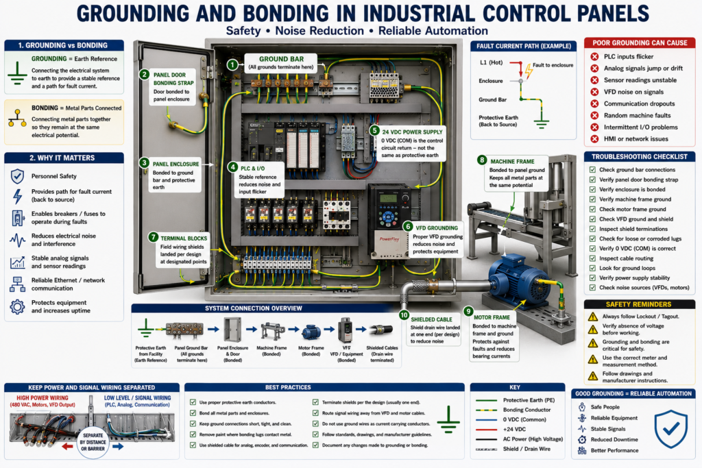
1. Grounding vs Bonding
Grounding
Grounding connects an electrical system to earth reference.
Simple definition:
Grounding = Connecting the electrical system to earth reference.Grounding helps stabilize the system voltage and provides a reference point for fault protection.
Bonding
Bonding connects metal parts together so they remain at the same electrical potential.
Simple definition:
Bonding = Connecting conductive metal parts together.Bonding helps create a low-resistance path for fault current.
Examples:
Panel enclosure bonded to ground bar
Panel door bonded to enclosure
Machine frame bonded to ground
Motor frame bonded to equipment grounding conductor
Cable tray bonded to ground
VFD shield termination bonded correctly
A simple way to remember:
Grounding connects to earth.
Bonding connects metal parts together.
2. Why Grounding and Bonding Matter
Grounding and bonding are not only about code compliance.
They are also about real machine reliability.
Good grounding and bonding help with:
Personnel safety
Fault current return path
Breaker or fuse operation during faults
Reduced electrical noise
Stable analog signals
Reliable Ethernet communication
Reduced VFD interference
Reduced nuisance PLC input flickering
Protection of electrical equipment
Poor grounding and bonding can create strange problems:
PLC inputs flicker randomly
Analog values jump or drift
Sensors behave intermittently
HMI or PLC communication drops
VFD causes noise on nearby wiring
Ethernet faults appear randomly
Remote I/O faults intermittently
Touchscreen behaves erratically
Machine faults without obvious reason
These issues can be difficult to troubleshoot because the cause may not be a bad sensor or bad PLC module.
The cause may be the electrical installation.
3. Protective Earth
Protective earth is the safety grounding conductor.
It is usually identified by:
Green wire
Green/yellow wire
PE symbol
Ground symbol
Protective earth connects exposed metal parts to ground.
Examples:
Control panel enclosure
Panel door
Machine frame
Motor frame
VFD chassis
Power supply frame
Cable trays
Metal junction boxes
If a live conductor touches a metal enclosure, the protective earth path allows fault current to flow back to the source.
This high fault current should trip the breaker or blow the fuse.
Without a proper bonding path, the metal enclosure could remain energized and dangerous.
4. The Ground Bar
The ground bar is one of the most important points inside a control panel.
It usually connects:
Incoming protective earth
Panel enclosure
Panel door bonding strap
Machine frame ground
Motor ground conductors
VFD ground conductors
Power supply ground
Shield drain wires, when designed that way
The ground bar should be clean, tight, labeled, and properly bonded to the enclosure.
A loose ground bar connection can create safety and reliability problems.
5. Panel Door Bonding
The panel door should be bonded to the main enclosure.
Why?
Because the door may contain:
HMI
Pilot lights
Push buttons
Selector switches
E-stop buttons
Metal hardware
Ethernet ports
USB ports
If the door is not bonded, it may not have a reliable fault current path.
A bonding strap or grounding conductor is commonly used between the door and the enclosure.
Technician check:
Door bonded to enclosure?
Bonding strap tight?
Paint removed where bonding hardware contacts metal?
No broken or loose bonding wire?
6. Machine Frame Bonding
The machine frame should also be bonded.
A control panel often controls devices mounted on a larger machine structure.
Examples:
Conveyor frame
Motor base
Pump skid
Filler frame
Packaging machine frame
Robot cell frame
Metal guards
Remote junction boxes
Bonding the machine frame helps ensure all exposed conductive parts are at the same potential.
This improves safety and can reduce noise-related problems.
7. Motor Grounding
Motors must be properly grounded and bonded.
A motor usually has:
Power leads
Ground conductor
Motor frame grounding point
The motor frame ground is critical.
If a winding faults to the motor frame, the grounding conductor provides a path for fault current.
This should cause protection to operate.
Poor motor grounding can be dangerous and can also increase electrical noise.
With VFD-driven motors, grounding becomes even more important because VFD outputs produce high-frequency switching noise.
8. VFD Grounding and Noise
VFDs are common sources of electrical noise.
A VFD uses high-speed switching to create variable frequency output power to the motor.
This can create:
Electrical noise
Common-mode current
EMI
Ground noise
Motor bearing currents
Communication interference
Analog signal instability
Good VFD installation practices include:
Proper VFD grounding
Correct motor cable grounding
Shielded motor cable when required
Proper shield termination
Separation between power and signal wiring
Short grounding paths
Following manufacturer installation instructions
Do not route VFD output wiring next to sensitive analog or communication wiring unless the panel design specifically accounts for it.
9. Shielded Cable and Drain Wires
Shielded cable is used to reduce electrical noise.
Common shielded cable applications:
Analog signals
4–20 mA transmitters
0–10 VDC signals
Thermocouples
RTDs
Encoder cables
VFD motor cables
Communication cables
Servo cables
The shield helps block or drain unwanted electrical noise.
A shield drain wire may be connected to ground depending on the system design.
Important:
Follow the machine documentation and manufacturer recommendations.
Do not randomly land shield wires without understanding the design.
Incorrect shield grounding can create ground loops or noise problems.
10. Ground Loops
A ground loop can happen when a signal has more than one ground reference path.
This can cause unwanted current to flow through signal wiring or shields.
Possible symptoms:
Analog signal drifting
Noisy 4–20 mA loop
Unstable 0–10 VDC signal
Communication issues
Sensor signal instability
Random measurement errors
Ground loops are especially common in analog instrumentation and communication systems when grounding is not designed properly.
Technician mindset:
Do not assume every shield or common should be connected everywhere.
Follow the drawing and standard.
11. 0 VDC Common Is Not the Same as Protective Earth
This is a very important concept.
In 24 VDC systems, you have:
+24 VDC
0 VDC / Common
Protective Earth / Ground
The 0 VDC common is the return path for the DC control circuit.
Protective earth is the safety grounding system.
They may be connected at one point depending on the design, but they are not the same thing.
Do not randomly jumper 0 VDC to ground unless the drawing or standard design requires it.
Incorrect bonding of 0 VDC to ground can create noise, ground loops, or troubleshooting problems.
12. Grounding and Analog Signals
Analog signals are more sensitive than basic digital signals.
Examples:
4–20 mA pressure transmitter
0–10 VDC level signal
Thermocouple temperature signal
RTD temperature signal
Load cell signal
Conductivity probe
pH transmitter
Poor grounding can cause analog values to:
Jump
Drift
Read incorrectly
Spike
Become noisy
Drop out
Show unstable trends on HMI/SCADA
When troubleshooting analog problems, check:
Shield wiring
Grounding points
Loose terminals
Power supply stability
Signal common
Cable routing
VFD cable proximity
Instrument grounding
Analog card common
13. Grounding and Industrial Networks
Industrial networks can also be affected by poor bonding and noise.
Examples:
EtherNet/IP
Profinet
Modbus TCP
Remote I/O networks
Encoder feedback networks
Servo networks
Vision system networks
Possible symptoms:
Communication faults
Remote I/O dropouts
VFD communication loss
HMI losing connection
Random Ethernet faults
Intermittent device timeouts
Common causes may include:
Poor bonding
Noise from VFD cables
Bad shield termination
Bad Ethernet cable routing
Damaged cable shield
Panel not bonded correctly
Different ground potentials between panels
Good bonding between panels and machine sections helps reduce these issues.
14. Testing Grounding and Bonding
Testing grounding and bonding depends on plant procedures, safety rules, and the type of equipment.
Common technician-level checks include:
Visual inspection
Continuity check
Bonding strap inspection
Ground bar inspection
Loose terminal check
Ground conductor verification
Panel door bonding check
Motor frame bonding check
Machine frame bonding check
Shield drain wire inspection
For more formal testing, specialized equipment and qualified procedures may be required.
Basic continuity concept
A technician may verify that exposed metal parts are bonded together with low resistance.
Examples:
Panel door to ground bar
Panel enclosure to ground bar
Motor frame to ground bar
Machine frame to panel ground
Junction box to machine frame
Important:
Always follow plant electrical safety procedures.
Never perform resistance tests on live circuits.
Use the correct meter and method.
15. Common Grounding and Bonding Problems
Common issues include:
Loose ground terminals
Broken bonding straps
Paint under ground lugs
Corroded ground connections
Missing motor ground
Disconnected shield drain wires
Shields grounded incorrectly
Poor VFD cable grounding
Panel door not bonded
Machine frame not bonded
Multiple improper 0 VDC-to-ground bonds
Ground wires used incorrectly as current-carrying conductors
Ground bar not bonded properly to enclosure
These issues may create both safety hazards and troubleshooting headaches.
16. Troubleshooting Example: Analog Signal Jumping
Problem
A pressure transmitter signal on the HMI jumps randomly.
Possible causes:
Noisy analog signal
Loose signal wire
Bad transmitter
Bad analog input card
Unstable 24 VDC power
Bad shield grounding
VFD noise coupling into signal cable
Ground loop
Troubleshooting path
Check transmitter power.
Check 4–20 mA signal with meter or loop calibrator.
Inspect shielded cable.
Check shield termination.
Verify cable is not routed with VFD output wiring.
Check analog input card common.
Check grounding and bonding.
Compare reading at field device and PLC.
The issue may not be the transmitter.
It may be grounding, shielding, or noise.
17. Troubleshooting Example: Random PLC Input Flicker
Problem
A PLC input flickers ON and OFF even when the sensor is stable.
Possible causes:
Loose common wire
Electrical noise
Bad sensor cable
Improper grounding
VFD noise
Inductive load without suppression
Input wiring routed near power wiring
Bad input module
Troubleshooting path
Check sensor power.
Check signal at sensor.
Check signal at terminal block.
Check PLC input LED.
Check 0 VDC common.
Inspect cable routing.
Check for nearby VFD/motor wiring.
Check grounding and bonding.
Check relay or solenoid suppression.
Again, the PLC program may not be the problem.
18. Best Practices
Good grounding and bonding practices include:
Use proper protective earth conductors.
Bond panel doors to enclosures.
Bond machine frames.
Ground motor frames.
Keep ground connections clean and tight.
Remove paint where bonding hardware requires metal contact.
Use proper lugs and hardware.
Follow VFD installation guidelines.
Separate power wiring from signal wiring.
Use shielded cable where required.
Terminate shields according to the design.
Avoid random grounding changes.
Follow drawings and plant standards.
Document corrections.
A good technician does not randomly move ground wires to “see if it works.”
Grounding changes should be intentional, documented, and based on drawings or engineering guidance.
19. Technician Checklist
When inspecting grounding and bonding, verify:
Ground bar is present and bonded.
Incoming protective earth is connected.
Panel enclosure is bonded.
Panel door bonding strap is installed.
Machine frame is bonded.
Motor frame grounds are connected.
VFD ground connections are correct.
Shield drain wires are landed correctly.
No loose or corroded ground terminals.
No broken bonding straps.
No paint prevents metal-to-metal bonding.
0 VDC common is handled according to the design.
Power and signal wiring are separated where possible.
Analog cables are shielded where required.
Network cables are routed away from high-noise wiring.
Final Thoughts
Grounding and bonding are not optional details.
They are essential for electrical safety, fault clearing, noise reduction, and reliable automation.
A strong automation technician understands that grounding and bonding affect more than just safety.
They can affect PLC inputs, analog signals, VFDs, networks, HMIs, sensors, and communication systems.
When a machine has random, intermittent, or noise-related problems, do not only blame the PLC.
Check the installation.
Check the ground bar.
Check the bonding straps.
Check the motor grounds.
Check the shields.
Check the VFD wiring.
Check the common.
Check the cable routing.
Good grounding and bonding protect people, protect equipment, and help automation systems run reliably.