5. Ladder Logic Basics in Studio 5000
Ladder Logic Basics in Studio 5000
Ladder logic is one of the most important programming languages for automation technicians and PLC programmers to understand.
Even though Studio 5000 Logix Designer supports multiple programming languages, ladder logic is still widely used in industrial automation because it is visual, practical, and easier to troubleshoot during real machine problems.
For a technician, ladder logic answers a very important question:
Why is this output ON or OFF?When a motor does not start, a valve does not open, or a conveyor does not run, ladder logic helps you follow the control conditions step by step.
Rockwell’s Studio 5000 lab manual uses ladder logic as the first programming example. The lab walks through adding basic instructions such as XIC, XIO, OTE, and a branch to create a simple motor start/stop seal-in circuit.
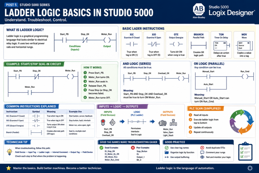
What Is Ladder Logic?
Ladder logic is a graphical PLC programming language that looks similar to electrical relay logic.
It uses two vertical power rails and horizontal rungs.
A simple ladder rung can be understood like this:
Conditions on the left → Output on the rightExample:
Start_PB       Stop_OK       Motor_Run
----] [----------] [------------( )----
Simple meaning:
If Start_PB is true
AND Stop_OK is true
THEN turn on Motor_Run
This visual style makes ladder logic useful for electricians, technicians, and controls engineers because it resembles how control circuits are wired.
Why Ladder Logic Is Still Important
Ladder logic is still common because it is very useful for troubleshooting discrete machine logic.
It is commonly used for:
Motors
Solenoid valves
Push buttons
Selector switches
Limit switches
Photo eyes
Proximity sensors
Permissives
Interlocks
Faults
Alarms
Machine states
Output commands
For example, if a conveyor is not starting, ladder logic helps you see which condition is missing:
Start command?
Stop circuit healthy?
E-stop reset?
Motor overload OK?
VFD ready?
No jam fault?
Auto mode selected?
This is why ladder logic is not just programming. It is also a troubleshooting tool.
Basic Ladder Instructions
The first instructions every technician should understand in Studio 5000 are:
| Instruction | Name | Simple Meaning |
|---|---|---|
| XIC | Examine If Closed | True when the tag is ON/1 |
| XIO | Examine If Open | True when the tag is OFF/0 |
| OTE | Output Energize | Turns a bit ON when rung is true |
| Branch | Parallel path | Creates OR logic |
| TON | Timer On Delay | Delays an action after conditions are true |
| MOV | Move | Copies a value into another tag |
In this post, we will focus on the first four:
XIC
XIO
OTE
Branch
These are the foundation of basic ladder logic.
1. XIC — Examine If Closed
The XIC instruction is one of the most common ladder instructions.
It looks like this:
----] [----Simple rule:
XIC is true when the tag is ON.Example:
DI_Start_PB
----] [----
If DI_Start_PB = 1, the instruction is true.
If DI_Start_PB = 0, the instruction is false.
Technician Explanation
Think of XIC as asking:
Is this condition ON?Examples:
Is the start push button pressed?
Is the proximity sensor detecting?
Is the motor feedback ON?
Is Auto Mode active?
Is the VFD Ready bit ON?
2. XIO — Examine If Open
The XIO instruction looks like this:
----]/[----Simple rule:
XIO is true when the tag is OFF.Example:
Motor_Fault
----]/[----
If Motor_Fault = 0, the instruction is true.
If Motor_Fault = 1, the instruction is false.
Technician Explanation
Think of XIO as asking:
Is this condition NOT active?Examples:
No fault active?
No jam detected?
No overload fault?
Stop button not pressed?
Photo eye not blocked?
This is very common in interlock and fault logic.
3. OTE — Output Energize
The OTE instruction looks like this:
----( )----Simple rule:
OTE turns the output bit ON when the rung is true.
OTE turns the output bit OFF when the rung is false.
Example:
Start_PB       Stop_OK       Motor_Run
----] [----------] [------------( )----
If all conditions before the OTE are true, Motor_Run turns ON.
If any condition becomes false, Motor_Run turns OFF.
Important Technician Note
An OTE is not a latch.
It only stays ON while the rung conditions are true.
If the rung goes false, the OTE goes false.
That makes OTE useful for normal command logic like:
Motor_Run_Cmd
Valve_Open_Cmd
Conveyor_Enable
Stack_Light_Green
4. Branch — Parallel Logic
A branch creates a parallel path in ladder logic.
A branch is used when you need OR logic.
Example:
Start_PB
----] [----------------------( Motor_Run )
       |
       | Motor_Run
       ----] [----
Simple meaning:
Start_PB OR Motor_Run can keep the rung true.The Studio 5000 lab manual demonstrates adding a branch around the XIC instruction as part of a simple start/stop motor circuit.
Branches are very important for:
Seal-in circuits
Multiple start conditions
Bypass logic
Manual or auto commands
Alternate permissive paths
Alarm conditions
Understanding AND Logic
In ladder logic, instructions in series create AND logic.
Example:
Start_PB       Stop_OK       Overload_OK       Motor_Run
----] [----------] [------------] [--------------( )----
Simple meaning:
Start_PB must be true
AND Stop_OK must be true
AND Overload_OK must be true
THEN Motor_Run turns ON
If any one condition is false, the output will not turn on.
This is common for permissives.
Example:
Auto_Mode
Safety_OK
Air_Pressure_OK
No_Fault
All must be true before the machine can run.
Understanding OR Logic
Parallel branches create OR logic.
Example:
Manual_Start
----] [----------------------( Run_Cmd )
       |
Auto_Start
----] [----
Simple meaning:
Manual_Start OR Auto_Start can turn on Run_Cmd.OR logic is common when more than one condition can request the same action.
Examples:
Manual open command OR auto open command
HMI start OR local start
Fault reset push button OR HMI reset
Alarm from motor OR alarm from sensor
The Classic Start/Stop Seal-In Circuit
One of the first ladder circuits to learn is the start/stop seal-in circuit.
Conceptual example:
Start_PB       Stop_OK       Motor_Run
----] [----------] [------------( )----
       |                      |
       | Motor_Run            |
       ----] [----------------|
Simple operation:
- Press
Start_PB. Motor_Runturns ON.- The
Motor_Runcontact seals around the start button. - When
Start_PBis released,Motor_Runstays ON. - If
Stop_OKturns false,Motor_Runturns OFF.
This is very similar to relay control logic.
The Studio 5000 lab manual uses a simple motor start/stop seal-in circuit as the first ladder logic exercise.
Why the Seal-In Circuit Works
The seal-in circuit works because the output bit is used as a holding condition.
When the operator presses Start:
Start_PB = 1
Stop_OK = 1
Motor_Run turns ON
Then the motor run bit holds itself:
Motor_Run = 1
Stop_OK = 1
Rung stays true
When Stop is pressed or the stop circuit opens:
Stop_OK = 0
Rung goes false
Motor_Run turns OFF
This is the foundation of many motor control circuits.
Normally Open vs Normally Closed Field Devices
This is where many beginners get confused.
The ladder instruction does not always match the physical contact type.
For example, a stop push button is often physically wired as a normally closed device for fail-safe behavior.
But in the PLC, the input may be ON when the stop circuit is healthy.
So the tag may be named:
DI_Stop_OKThen the ladder uses XIC:
DI_Stop_OK
----] [----
Meaning:
The stop circuit is healthy.This is clearer than naming it Stop_PB.
Good tag naming reduces confusion.
Recommended Technician Naming Style
Use tag names that describe the signal condition clearly.
Better:
DI_Stop_OK
DI_EStop_OK
DI_Guard_Door_Closed
DI_Motor_OL_OK
Instead of:
Stop_Button
EStop
Door
Overload
Why?
Because the tag name tells you what true means.
Example:
DI_EStop_OK = 1This clearly means the E-stop circuit is healthy.
That makes ladder logic easier to read.
Inputs, Logic, and Outputs
A good way to understand ladder logic is to think in three sections:
Inputs → Logic → OutputsExample:
Inputs:
DI_Start_PB
DI_Stop_OK
DI_Overload_OK

Logic:
Start/stop seal-in
Permissive check
Fault check

Output:
DO_Motor_Starter
For troubleshooting, follow this path:
Field input device
→ PLC input tag
→ Ladder condition
→ Internal command
→ PLC output tag
→ Field output device
This method is very practical in real industrial troubleshooting.
Internal Bits vs Physical Outputs
A professional Studio 5000 program usually does not write directly to physical outputs everywhere in the logic.
Better structure:
Motor_Run_Cmd  → internal command
DO_Motor_Run   → physical output
Example:
Start/Stop Logic
---- conditions ----------------( Motor_Run_Cmd )

Output Buffering
---- Motor_Run_Cmd -------------( DO_Motor_Run )
This separates decision logic from physical output mapping.
It makes the program cleaner and easier to troubleshoot.
Why Output Buffering Helps
Output buffering helps because:
All logic decisions happen before the physical output is mapped.
Outputs are easier to find.
Duplicate output problems are reduced.
Troubleshooting becomes cleaner.
Example:
Motor_Control routine:
Creates Motor_Run_Cmd

Output_Buffering routine:
Maps Motor_Run_Cmd to Local:2:O.Data.0
This is more industrial than energizing the same physical output from many different routines.
Common Beginner Mistake: Duplicate OTEs
A common mistake is using the same OTE tag in multiple places.
Example:
Rung 1:
---- Condition_A ----------------( Motor_Run )

Rung 10:
---- Condition_B ----------------( Motor_Run )
This can cause problems because the last scanned rung can overwrite the previous rung.
Better approach:
Condition_A → Motor_Start_Request
Condition_B → Motor_Auto_Request

Motor_Start_Request OR Motor_Auto_Request → Motor_Run_Cmd
Then use only one final OTE for the command.
This makes the logic easier to understand.
Ladder Logic and the PLC Scan
The PLC reads and solves ladder logic repeatedly.
A simplified scan is:
Read inputs
Execute ladder logic from top to bottom
Update outputs
Repeat
This matters because rung order can affect behavior.
For example:
If a bit is turned on in rung 5,
it can be used by rung 6 in the same scan.
But if rung 6 is above rung 5, the result may not appear until the next scan.
That is why program organization matters.
Technician Troubleshooting Example
Problem:
Motor does not start.
A basic ladder troubleshooting workflow:
1. Check DI_Start_PB.
   Does it turn ON when the start button is pressed?

2. Check DI_Stop_OK.
   Is the stop circuit healthy?

3. Check DI_Overload_OK.
   Is the overload reset and healthy?

4. Check Motor_Fault.
   Is a fault preventing operation?

5. Check Motor_Run_Cmd.
   Is the PLC logic commanding the motor?

6. Check DO_Motor_Starter.
   Is the physical output turning ON?

7. Check motor feedback.
   Did the starter or VFD actually run?
This is how ladder logic connects software troubleshooting to real field devices.
Simple Motor Logic Example
Here is a simple conceptual version:
Rung 1 — Motor Run Command

Start_PB        Motor_Run_Cmd
----] [-------------] [----------------
       |                              |
       | Motor_Run_Cmd                |
       ----] [------------------------|

Stop_OK        Overload_OK       No_Fault       Motor_Run_Cmd
----] [----------] [--------------] [------------( )----
Meaning:
The motor can run when:
Start is pressed or the motor is already running,
AND stop circuit is OK,
AND overload is OK,
AND no fault is active.
This style is easy to expand with more industrial conditions.
More Industrial Version
A more industrial motor command may include:
Auto_Mode
Manual_Mode
HMI_Start_Cmd
Local_Start_PB
Stop_OK
EStop_OK
Overload_OK
VFD_Ready
No_Fault
Permissive_OK
Interlock_OK
Example structure:
Start_Request = Local_Start_PB OR HMI_Start_Cmd OR Auto_Start_Request

Run_Permissive = Stop_OK AND EStop_OK AND Overload_OK AND VFD_Ready

Motor_Run_Cmd = Start_Request AND Run_Permissive AND No_Fault
This is easier to troubleshoot than placing every condition in one massive rung.
What a Technician Should Practice First
Before moving into advanced instructions, practice these fundamentals:
XIC
XIO
OTE
Branches
Seal-in circuits
AND logic
OR logic
Tag monitoring
Input-to-output troubleshooting
Basic rung comments
Cross reference
Once these are clear, instructions like timers, counters, MOV, comparisons, UDTs, and AOIs become easier to understand.
Good Rung Comments
A good rung comment explains the intent.
Poor comment:
Motor run rung.Better comment:
Creates the motor run command when a start request is active,
the stop circuit is healthy, and no motor fault is present.
Another example:
Maps the internal motor run command to the physical starter output.
All output mapping is kept in the output buffering routine.
Good comments help the next technician troubleshoot faster.
Final Thoughts
Ladder logic is the foundation of PLC troubleshooting in Studio 5000.
For a PLC programmer, ladder logic is used to build machine control behavior.
For an automation technician, ladder logic is used to understand why a machine is or is not doing something.
Start with the basics:
XIC = Is this ON?
XIO = Is this OFF?
OTE = Turn this bit ON when the rung is true.
Branch = OR logic / alternate path.
Then build toward real industrial logic:
Inputs
Permissives
Interlocks
Commands
Outputs
Feedback
Faults
Alarms
A technician who understands basic ladder logic can troubleshoot faster, communicate better with engineers, and understand machine behavior more clearly.