6. Tags in Studio 5000: Why Logix Does Not Use N7:0 Style Addresses
One of the biggest differences between older Allen-Bradley PLC platforms and Studio 5000 Logix Designer is the way memory is identified.
In older PLC systems, you may see addresses like:
B3:0/0
N7:0
T4:0
C5:0
I:1/0
O:2/0
In Studio 5000 Logix Designer, you normally work with tags instead.
Examples:
Motor_Start_PB
Motor_Stop_OK
Motor_Run_Cmd
Tank_Level
Conveyor_Running_FB
Door_Open_LS
Rockwell’s Studio 5000 lab manual explains that older PLCs identify data with physical memory addresses such as N7:0, but Logix controllers do not use a fixed numeric memory format. Instead, Logix controllers use tags that can be given meaningful names.
What Is a Tag?
A tag is a named memory location inside the controller.
Simple definition:
A tag is a name for data in the PLC.That data can represent many things:
A push button
A motor command
A valve feedback
A timer
A counter
A speed reference
A temperature value
A machine state
A fault bit
An alarm bit
The lab manual describes a tag as a text-based name for an area of memory. It also explains that tag names help document ladder code and organize data around the machinery.
That is very important.
A good tag name can tell you what the logic is doing before you even read the rung comment.
Old Address Style vs New Tag Style
In older PLC platforms, you may need to know what a memory address means.
Example:
B3:0/0That address does not explain much by itself.
You need documentation to know if it means:
Motor run command?
Fault reset?
Start push button?
Alarm bit?
In Studio 5000, a tag name can describe the signal directly.
Example:
Motor_Run_CmdThis immediately tells you the purpose of the bit.
Comparison:
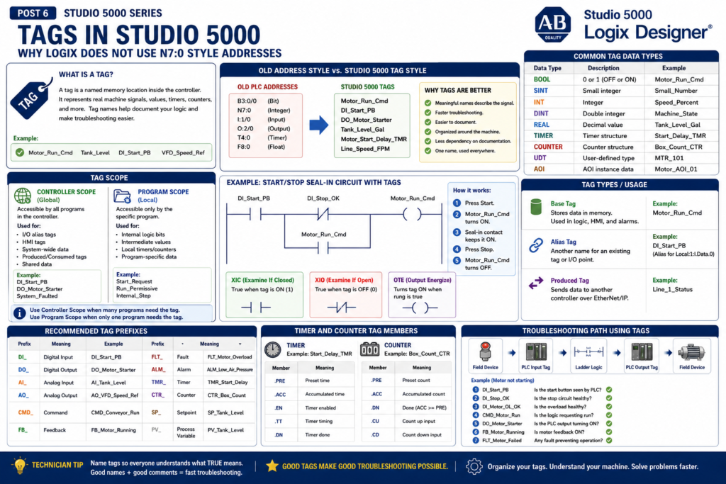
| Older Address Style | Studio 5000 Tag Style |
|---|---|
B3:0/0 | Motor_Run_Cmd |
I:1/0 | DI_Start_PB |
O:2/0 | DO_Motor_Starter |
N7:0 | Machine_State |
F8:0 | Tank_Level_Gallons |
T4:0 | Motor_Start_Delay_TMR |
The tag-based system makes the program easier to understand and troubleshoot.
Why Tags Are Better for Technicians
Tags are easier to troubleshoot because they describe real machine signals.
For example, during a breakdown, compare these two situations:
Old Style
B3:5/12 is OFF.You still need to ask:
What is B3:5/12?
Where is it used?
What does it represent?
Tag Style
Motor_Overload_OK is OFF.Now the meaning is much clearer.
You immediately know the motor overload condition is not healthy.
This helps technicians move faster from software troubleshooting to real field troubleshooting.
Tags Help Connect the PLC to the Machine
A good tag name should connect the logic to the physical machine.
Example:
DI_Start_PB
DI_Stop_OK
DI_Photoeye_Clear
DI_Guard_Door_Closed
DO_Conveyor_Motor
DO_StackLight_Green
AI_Tank_Level
AO_VFD_Speed_Reference
These tags help answer questions like:
Is the start push button being seen by the PLC?
Is the stop circuit healthy?
Is the photo eye blocked?
Is the guard door closed?
Is the PLC commanding the conveyor?
Is the analog level signal changing?
Is the VFD speed reference being sent?
This is why tag naming is not just a programming preference. It is a troubleshooting tool.
Common Tag Data Types
A tag also has a data type.
The data type defines what kind of value the tag can store.
Common Studio 5000 data types include:
| Data Type | Meaning | Example |
|---|---|---|
| BOOL | 0 or 1 / OFF or ON | Motor_Run_Cmd |
| SINT | Small integer | Small numeric values |
| INT | Integer | General whole numbers |
| DINT | Double integer | Machine states, counters, indexes |
| REAL | Decimal value | Temperature, pressure, speed |
| TIMER | Timer structure | Start_Delay_TMR |
| COUNTER | Counter structure | Box_Count_CTR |
| UDT | User-defined structure | MTR_101 |
| AOI-defined type | Add-On Instruction instance data | Motor_AOI_01 |
For a technician, the most common ones to understand first are:
BOOL
DINT
REAL
TIMER
COUNTER
UDT
BOOL Tags
A BOOL tag is a single bit.
It can be:
0 = OFF / False
1 = ON / True
BOOL tags are used for discrete signals:
Start push button
Stop status
Motor command
Valve command
Sensor status
Fault active
Alarm active
Mode selected
Examples:
DI_Start_PB
DI_Stop_OK
Motor_Run_Cmd
Valve_Open_FB
Machine_Faulted
In ladder logic, BOOL tags are commonly used with:
XIC
XIO
OTE
OTL
OTU
ONS
DINT Tags
A DINT is a whole number.
It is commonly used for:
Machine states
Counters
Step numbers
Recipe numbers
Fault codes
Mode numbers
Index values
Examples:
Machine_State
Active_Step
Fault_Code
Recipe_Number
Box_Count
A DINT is useful when you want one tag to represent a state or number.
Example:
Machine_State = 0  → Idle
Machine_State = 10 → Starting
Machine_State = 20 → Running
Machine_State = 30 → Stopping
Machine_State = 40 → Faulted
This is very common in more professional Studio 5000 programs.
REAL Tags
A REAL tag stores a decimal value.
It is commonly used for analog signals and calculated values.
Examples:
Tank_Level_Gal
Line_Speed_FPM
Motor_Current_Amp
Temperature_DegF
Pressure_PSI
Flow_GPM
REAL tags are important when working with:
Analog inputs
Analog outputs
Scaling
PID loops
VFD speed references
Process values
Setpoints
Example:
AI_Tank_Level_Raw      = raw input value
Tank_Level_Percent    = scaled engineering value
Tank_Level_Setpoint   = target value
TIMER Tags
In Studio 5000, timers are tags.
A timer tag contains several members.
Example:
Motor_Start_Delay_TMRCommon timer members:
Motor_Start_Delay_TMR.PRE
Motor_Start_Delay_TMR.ACC
Motor_Start_Delay_TMR.EN
Motor_Start_Delay_TMR.TT
Motor_Start_Delay_TMR.DN
Meaning:
| Timer Member | Meaning |
|---|---|
.PRE | Preset time |
.ACC | Accumulated time |
.EN | Timer enabled |
.TT | Timer timing |
.DN | Timer done |
Example:
Motor_Start_Delay_TMR.DNThis means the timer has finished timing.
COUNTER Tags
Counters also use structured tag members.
Example:
Box_Count_CTRCommon counter members:
Box_Count_CTR.PRE
Box_Count_CTR.ACC
Box_Count_CTR.DN
Counters are commonly used for:
Box counting
Cycle counting
Part counting
Batch counting
Reject counting
Maintenance counts
Example:
Box_Count_CTR.ACCThis is the current accumulated count.
Controller Scope vs Program Scope
This is one of the most important Studio 5000 tag concepts.
When you create a tag, you must decide where the tag lives.
There are two common scopes:
Controller Scope
Program Scope
Rockwell’s lab manual explains that controller-scoped tags are accessible by all programs, while parameters and local tags are accessible only by the code within a specific program. It also explains that local tags are isolated from other programs and that this isolation can help prevent tag name collisions and improve code reuse.
Controller-Scoped Tags
Controller-scoped tags are global.
Any program in the controller can access them.
Common uses:
Physical I/O alias tags
HMI interface tags
System-wide status
Produced and consumed tags
Shared data between programs
Controller-level fault summary
Examples:
DI_Start_PB
DO_Motor_Starter
HMI_Start_Cmd
System_Faulted
Line_Running
Use controller scope when the tag needs to be shared across the project.
Program-Scoped Tags
Program-scoped tags are local to a specific program.
Only that program can access them.
Common uses:
Internal logic bits
Intermediate calculations
Local sequence bits
Program-specific timers
Program-specific counters
Temporary values
Examples:
Start_Request
Run_Permissive
Internal_Step
Fault_Timer
OneShot_Start
Use program scope when the tag is only needed inside one program.
This helps keep the project clean and prevents unnecessary global tags.
Simple Scope Example
Imagine you have two conveyors:
Conveyor_1
Conveyor_2
Each conveyor program may use local tags like:
Start_Request
Run_Command
Fault_Timer
Because they are program-scoped, the same local names can exist in both programs without conflict.
Example:
Conveyor_1.Start_Request
Conveyor_2.Start_Request
This makes code easier to reuse.
Base Tags and Alias Tags
When creating a tag in Studio 5000, you may see different tag types or usages.
The lab manual explains several tag attributes, including Base, Alias, and Produced. It describes a base tag as one that stores values for use by logic, an alias as a tag that represents another tag, and a produced tag as data sent to another controller.
Let’s explain these simply.
Base Tag
A base tag is a normal tag that stores data.
Example:
Motor_Run_CmdThis tag has its own memory location.
It can be used in logic, monitored, written to, and referenced by other tags or instructions.
Most internal tags are base tags.
Alias Tag
An alias tag is another name for an existing tag or I/O point.
Example:
DI_Start_PB → Local:1:I.Data.0The alias tag does not create new memory.
It points to another tag.
This makes raw I/O easier to read.
Instead of using:
Local:1:I.Data.0You use:
DI_Start_PBThat is much easier for troubleshooting.
Why Alias Tags Are Useful for I/O
Raw I/O tags can be hard to read.
Example:
Local:2:I.Data.5That does not clearly tell you what field device is connected.
Alias tag:
DI_Photoeye_ClearNow the meaning is clear.
The lab manual explains that I/O module tags are created in Controller Scope and that local modules are identified as “Local.”
That is why you often see raw I/O tags like:
Local:1:I.Data
Local:2:O.Data
A good project uses alias tags to make those raw points readable.
Produced Tags
A Produced Tag is used to send data to another controller.
Example:
Line_1_Status
Filler_Running
Tank_Level_Data
Produced/Consumed tags are common in larger systems where controllers share data over EtherNet/IP.
Simple idea:
Controller A produces data.
Controller B consumes that data.
For beginners, you do not need to master produced/consumed tags immediately, but you should recognize that they are used for controller-to-controller communication.
Recommended Tag Prefixes
A clean naming convention makes the program much easier to troubleshoot.
Here is a practical technician-friendly convention:
| Prefix | Meaning | Example |
|---|---|---|
DI_ | Digital Input | DI_Start_PB |
DO_ | Digital Output | DO_Motor_Starter |
AI_ | Analog Input | AI_Tank_Level_Raw |
AO_ | Analog Output | AO_VFD_Speed_Ref |
CMD_ | Command | CMD_Motor_Run |
FB_ | Feedback | FB_Motor_Running |
FLT_ | Fault | FLT_Motor_Overload |
ALM_ | Alarm | ALM_Low_Air_Pressure |
TMR_ | Timer | TMR_Start_Delay |
CTR_ | Counter | CTR_Box_Count |
SP_ | Setpoint | SP_Tank_Level |
PV_ | Process Variable | PV_Tank_Level |
You can adjust the convention based on your plant standard, but the key idea is consistency.
Good Tag Names vs Poor Tag Names
Poor Tag Names
Bit_1
Start
Motor
Output_4
Test
Aux
Sensor1
These names are too vague.
Better Tag Names
DI_Start_PB
DI_Stop_OK
DI_Motor_Overload_OK
CMD_Motor_Run
DO_Motor_Starter
FB_Motor_Running
FLT_Motor_Failed_To_Start
These names explain the signal’s purpose.
A technician should be able to understand the tag without constantly opening documentation.
Tag Naming Rule: Name What TRUE Means
This is one of the most important rules.
A BOOL tag should clearly describe what it means when it is 1.
Example:
DI_Stop_OK = 1This means the stop circuit is healthy.
That is clearer than:
Stop_Button = 1Because with stop buttons, people often get confused between the physical normally closed contact and the PLC logic state.
Better examples:
DI_EStop_OK
DI_Guard_Door_Closed
DI_Air_Pressure_OK
DI_Motor_OL_OK
DI_VFD_Ready
Now the ladder logic reads naturally:
E-stop OK
Guard door closed
Air pressure OK
Motor overload OK
VFD ready
That makes troubleshooting much easier.
Tag Descriptions Are Also Important
The tag name should be clear, but the tag description adds more context.
Example:
| Tag Name | Description |
|---|---|
DI_Start_PB | Local operator start push button input |
DI_Stop_OK | Stop circuit healthy status from NC stop circuit |
DO_Motor_Starter | Physical output to motor starter coil |
FB_Motor_Running | Motor running feedback from auxiliary contact |
FLT_Motor_Failed_To_Start | Latched fault when feedback does not prove after run command |
Good descriptions help maintenance and engineering understand the signal.
They also make online troubleshooting easier.
Technician Troubleshooting Example
Problem:
The conveyor does not start.
Use tags to troubleshoot step by step:
1. DI_Start_PB
   Does the PLC see the start button?

2. DI_Stop_OK
   Is the stop circuit healthy?

3. DI_EStop_OK
   Is the E-stop circuit reset?

4. DI_Motor_OL_OK
   Is the overload healthy?

5. CMD_Conveyor_Run
   Is the logic requesting the conveyor to run?

6. DO_Conveyor_Starter
   Is the PLC output turning on?

7. FB_Conveyor_Running
   Is the motor starter or VFD feedback returning?
This workflow follows the control path:
Input → Logic → Output → FeedbackThat is the heart of PLC troubleshooting.
Common Mistake: Using Raw I/O Everywhere
Avoid writing logic directly with raw I/O tags everywhere.
Example:
Local:1:I.Data.0
Local:2:O.Data.3
This works, but it is harder to read.
Better approach:
Local:1:I.Data.0 → DI_Start_PB
Local:2:O.Data.3 → DO_Motor_Starter
Then use the alias tags in the logic.
This makes the program easier to understand.
Common Mistake: No Naming Standard
Another common mistake is mixing styles:
StartButton
start_pb
PB_Start
DI_Start
Start_Input
All may mean the same thing, but the inconsistency makes the project harder to maintain.
Pick a standard and follow it.
Example:
DI_Start_PB
DI_Stop_OK
CMD_Motor_Run
DO_Motor_Starter
FB_Motor_Running
Consistency is more important than perfection.
Common Mistake: Global Tags for Everything
It is tempting to create every tag as controller-scoped.
But that can make the project messy.
Use controller scope for shared or global data.
Use program scope for local logic.
Simple rule:
If many programs need it, use controller scope.
If only one program needs it, use program scope.
This keeps the tag database cleaner.
Industrial Example: Motor Tags
A professional motor control section may use tags like:
DI_M101_Start_PB
DI_M101_Stop_OK
DI_M101_OL_OK
DI_M101_Run_FB

CMD_M101_Run
DO_M101_Starter

FLT_M101_Failed_To_Start
ALM_M101_Not_Available
TMR_M101_Start_FB
Or, in a more advanced project, these may be inside a UDT:
M101.Cmd.Run
M101.Fb.Running
M101.Flt.FailedToStart
M101.Alm.NotAvailable
M101.Tmr.StartFB
Both approaches are valid.
The UDT approach becomes cleaner when you have many similar motors.
Final Thoughts
Tags are one of the most important concepts in Studio 5000 Logix Designer.
Older PLC platforms use fixed memory addresses like:
N7:0
B3:0/0
I:1/0
O:2/0
Studio 5000 uses meaningful tag names like:
Motor_Run_Cmd
DI_Start_PB
Tank_Level
Machine_State
For a PLC programmer, tags help organize logic.
For an automation technician, tags make troubleshooting easier because they connect the software to the real machine.
Remember this simple idea:
Good tag names make good troubleshooting possible.A well-named tag should tell you:
What the signal is
Where it comes from
What it controls
What TRUE means
How it relates to the machine
Once you understand tags, Studio 5000 becomes much easier to read, monitor, and troubleshoot.