4. Understanding the Controller Organizer in Studio 5000
Understanding the Controller Organizer in Studio 5000
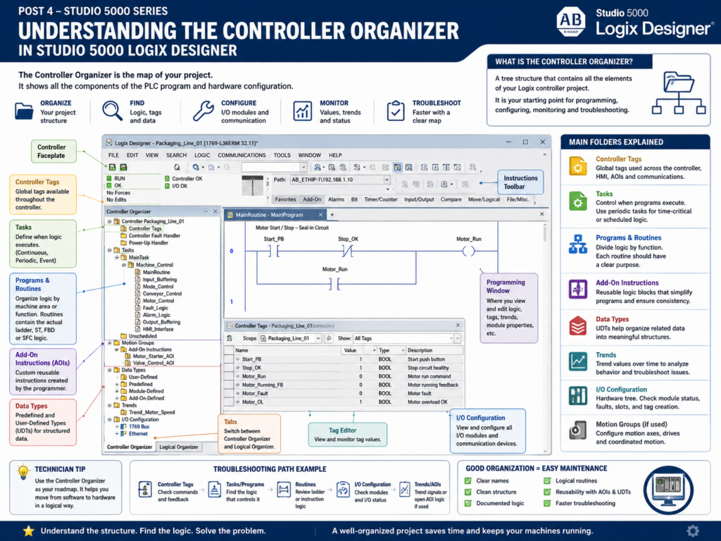
When you open a project in Studio 5000 Logix Designer, one of the most important areas is the Controller Organizer.
The Controller Organizer is the tree structure usually located on the left side of the Studio 5000 window. It acts like the main map of the PLC project.
From the Controller Organizer, you can find:
Controller Tags
Tasks
Programs
Routines
I/O Configuration
Add-On Instructions
Data Types
Trends
Motion Groups
For an automation technician, this area is extremely important because it helps you understand how the PLC project is organized before you start troubleshooting.
Rockwell’s Studio 5000 lab manual describes the Controller Organizer as a graphical representation of the controller file. It contains the folders and files that hold the programs and data in the current controller project.
Why the Controller Organizer Matters
A PLC program is not just a group of random ladder rungs.
A well-built Studio 5000 project has structure.
That structure helps you find:
Where the logic is located
Where the controller tags are stored
Where the I/O modules are configured
Where routines are organized
Where AOIs and UDTs are defined
Where trends may be saved
In the field, this matters because troubleshooting is faster when you know where to look.
For example, if a conveyor motor is not starting, you may need to check:
Controller Tags → motor command or fault tags
Tasks → which task is running the logic
Programs → which machine area contains the motor logic
Routines → where the ladder rungs are written
I/O Configuration → physical input/output modules
The Controller Organizer gives you a map of all these areas.
Controller Organizer vs Programming Window
Studio 5000 has different working areas.
The Controller Organizer shows the project structure.
The Programming Window shows the logic, tag editor, module properties, trends, or configuration window you are currently working on.
The lab manual identifies the Controller Organizer, Programming Window, I/O Configuration, instruction toolbar, controller faceplate, and Tasks/Programs/Routines areas as major parts of the Studio 5000 interface.
Simple explanation:
Controller Organizer = Where things are located

Programming Window = Where you view or edit the selected item
Example:
Click MainRoutine in Controller Organizer
→ Ladder logic opens in Programming Window

Click Controller Tags in Controller Organizer
→ Tag database opens in Programming Window

Click I/O Configuration in Controller Organizer
→ Hardware tree opens in Programming Window
Main Folders in the Controller Organizer
A typical Studio 5000 project contains several main folders.
The lab manual lists the default main folders as:
Controller File Name
Tasks
Motion Groups
Add-On Instructions
Data Types
Trends
I/O Configuration
It also explains that the plus or minus symbol is used to expand or collapse folders in the tree.
Let’s explain each one from a practical technician point of view.
1. Controller File Name
At the top of the Controller Organizer, you normally see the controller or project name.
Example:
Controller Line_3_Filler
Controller Freezer_Door_Control
Controller TankFarm_CLX01
This is the main project container.
Inside this area, you may find items such as:
Controller Tags
Controller Fault Handler
Power-Up Handler
The controller name helps identify what machine, line, or process area the PLC belongs to.
A good controller name should be meaningful.
Poor names:
PLC_1
Test
New_Project
Controller
Better names:
Line_2_Packaging_CLX
Freezer_Door_Control
TankFarm_Main_CLX01
CIP_System_CompactLogix
A good name helps the next technician understand the project faster.
2. Controller Tags
Controller Tags are global tags available throughout the controller.
These are tags that can be used by different programs, routines, HMI screens, communications, and sometimes other controllers.
Examples:
DI_Start_PB
DO_Motor_Starter
Tank_Level
Line_Running
System_Fault
HMI_Reset_Cmd
Controller Tags are commonly used for:
Physical I/O aliases
HMI interface tags
System-wide status bits
Produced/consumed tags
Shared machine data
Fault and alarm summary tags
From a troubleshooting point of view, Controller Tags are very important because they let you monitor live values.
If an input is not changing, a command is missing, or a fault bit is active, you may find it in Controller Tags.
3. Tasks
A Task controls when logic executes.
In Studio 5000, logic does not run randomly. It runs inside tasks.
A common basic project has:
MainTaskLarger projects may have multiple tasks:
MainTask
Fast_Task
Periodic_100ms
Motion_Task
Alarm_Task
Communication_Task
The lab manual includes a section on using periodic tasks and explains that tasks can be added from the Controller Organizer.
From a technician point of view, this matters because not all logic may execute at the same rate.
Example:
MainTask        → general machine logic
Fast_Task       → high-speed sensor logic
Periodic_500ms  → calculations or diagnostics
If you are troubleshooting a signal, it helps to know which task is scanning that logic.
4. Programs
A Program is a container inside a task.
A task can contain one or more programs.
Programs help organize logic by machine area, function, or process section.
Example:
MainTask
 ├── Conveyor_Control
 ├── Filler_Control
 ├── Alarm_Handling
 └── HMI_Interface
Each program can have its own:
Program Tags
Routines
Fault routine
Main routine
From a professional programming point of view, programs help keep logic organized.
Instead of putting everything in one large routine, you separate the control system into logical sections.
5. Routines
A Routine is where the actual logic is written.
Routines may contain:
Ladder Logic
Structured Text
Function Block Diagram
Sequential Function Chart
For many technicians, ladder routines are the most common.
Example routine structure:
Machine_Control
 ├── MainRoutine
 ├── Input_Buffering
 ├── Mode_Control
 ├── Permissive_Logic
 ├── Interlock_Logic
 ├── Fault_Logic
 ├── Alarm_Logic
 ├── Output_Buffering
 └── HMI_Status
A routine should have a clear purpose.
Good routine names:
Input_Buffering
Motor_Control
Valve_Control
Fault_Logic
Alarm_Logic
Output_Buffering
Poor routine names:
Routine1
Logic2
Test
Stuff
NewRoutine
A technician should be able to open a routine and quickly understand what type of logic is inside.
Recommended Industrial Routine Structure
For machine logic, a clean structure may look like this:
MainTask
 └── Machine_Control
      ├── MainRoutine
      ├── Input_Buffering
      ├── Mode_Control
      ├── Permissive_Logic
      ├── Interlock_Logic
      ├── Sequence_Logic
      ├── Fault_Logic
      ├── Alarm_Logic
      ├── Output_Buffering
      └── HMI_Interface
This makes the program easier to troubleshoot.
The idea is simple:
Read Inputs
Determine Mode
Check Permissives
Check Interlocks
Run Sequence
Detect Faults
Generate Alarms
Command Outputs
Update HMI Status
That is much cleaner than placing all logic in one huge MainRoutine.
6. I/O Configuration
The I/O Configuration folder shows the hardware structure of the controller system.
This is where you find:
Ethernet modules
Local I/O modules
Remote I/O adapters
Digital input modules
Digital output modules
Analog input modules
Analog output modules
Drives
Communication modules
Specialty modules
The lab manual identifies I/O Configuration as one of the main folders in the Controller Organizer.
From a technician point of view, I/O Configuration is critical.
This is where you can check:
Is the module configured?
Is the module faulted?
Is the module inhibited?
What slot is the module in?
What is the module name?
What IP address or communication path is used?
What input and output tags were created?
When a field device is not working, the I/O tree is one of the first areas to check.
Example: Troubleshooting from I/O Configuration
Imagine a proximity sensor is not being seen by the PLC.
You can use the Controller Organizer to follow the path:
I/O Configuration
 → Find the input module
 → Check module status
 → Open module-defined tags
 → Monitor the input bit
 → Compare with field voltage or sensor LED
This helps separate the problem:
Field device problem?
Wiring problem?
I/O module problem?
Network problem?
Logic problem?
That is why a technician should not only know ladder logic. They should also know the I/O tree.
7. Data Types
The Data Types folder contains predefined and user-defined data structures.
In Studio 5000, you will commonly see:
Predefined data types
User-Defined Types
Module-Defined data types
Add-On-Defined data types
The lab manual lists Data Types as one of the main folders in the Controller Organizer.
A UDT, or User-Defined Type, is a custom structure created by the programmer.
Example:
Motor_UDT
 ├── Start_Cmd
 ├── Stop_Cmd
 ├── Run_Cmd
 ├── Running_FB
 ├── Fault
 ├── Alarm
 └── Runtime_Hours
UDTs help organize related data.
Instead of creating many separate tags, you can create one structured motor tag:
MTR_101.Run_Cmd
MTR_101.Running_FB
MTR_101.Fault
MTR_101.Alarm
This is very common in professional Studio 5000 projects.
8. Add-On Instructions
The Add-On Instructions folder contains custom instructions created by the programmer or imported from another project.
An AOI is like a reusable custom function.
Example AOIs:
Motor_Starter_AOI
Valve_Control_AOI
Analog_Scaling_AOI
Pump_Control_AOI
Alarm_Handler_AOI
Rockwell’s AOI manual explains that Add-On Instructions are custom instructions designed and created for Logix Designer. It also explains that AOIs can be used in routines like built-in instructions by calling the instruction and assigning arguments to its parameters.
From a technician point of view, AOIs are important because much of the real logic may be inside the AOI.
If you only look at the rung where the AOI is called, you may see something like:
Motor_Starter_AOI(MTR_101)But the detailed logic may be inside the AOI definition.
That means troubleshooting may require:
Open AOI definition
View logic
Monitor with data context
Check parameters
Check outputs
Check internal status
We will cover AOIs deeply later in this series.
9. Trends
The Trends folder stores trend objects used to monitor values over time.
Trends are useful for troubleshooting signals that change too fast or too slowly to understand by watching a tag.
Examples:
Tank_Level
Motor_Current
Temperature
Pressure
Conveyor_Speed
Timer.ACC
The lab manual explains that Studio 5000 basic trending lets you view sampled data over time in a graphical display. It also notes that the sample rate can be configured from 10 milliseconds to 30 minutes, and trends can be saved as part of the project file.
For technicians, trends are very useful for:
Intermittent sensor issues
Analog signal drift
Timer behavior
Speed reference changes
Level or pressure changes
Startup/shutdown sequence analysis
A trend can show what happened before, during, and after a fault condition.
10. Motion Groups
The Motion Groups folder is used when the project includes motion control.
Not every project uses motion.
You may see motion groups in systems with:
Servo drives
Kinetix drives
Electronic gearing
Position control
Axis control
Coordinated motion
For a basic machine or process PLC, this folder may be empty.
For packaging machines, robotics support systems, indexing conveyors, or servo-driven equipment, this area may be very important.
Logical Organizer
Studio 5000 may also include a Logical Organizer tab.
The lab manual notes that the Logical Organizer is not used in the basic lab but exists to provide more flexibility when organizing large programs.
Simple explanation:
Controller Organizer = hardware/controller/project structure

Logical Organizer = custom organization view for larger projects
Most technicians start with the Controller Organizer because it shows the standard structure of the project.
Technician Workflow: How to Use the Controller Organizer
When troubleshooting a machine, use the Controller Organizer like a roadmap.
Example problem:
The motor does not start.
A good workflow:
1. Open Controller Tags.
   Check HMI start command, stop status, motor fault, run command.

2. Open I/O Configuration.
   Check input and output modules for faults.

3. Open Tasks.
   Find the program controlling the machine.

4. Open Programs and Routines.
   Locate Motor_Control, Fault_Logic, or Output_Buffering.

5. Search or Cross Reference the motor tag.
   Find where the command is generated.

6. Check AOIs if used.
   Open motor AOI logic or monitor the AOI instance.

7. Check Trends if the issue is intermittent.
   Trend command, feedback, and fault bits.
This method is better than randomly clicking through ladder rungs.
PLC Programmer Workflow: How to Organize a Project
From a programmer’s point of view, the Controller Organizer should be clean and intentional.
A good project structure should make sense to another person.
Recommended approach:
Use clear program names.
Use clear routine names.
Separate logic by function.
Keep I/O buffering in one area.
Keep fault logic organized.
Keep alarm logic organized.
Use UDTs for repeated device data.
Use AOIs for reusable device control.
Document routines and tags.
Poor organization creates maintenance problems.
Good organization helps technicians troubleshoot faster.
Simple Example: Well-Organized Machine Project
Controller Packaging_Line_01

Controller Tags
 ├── HMI_Start_Cmd
 ├── HMI_Stop_Cmd
 ├── Line_Running
 ├── Line_Faulted
 └── Line_Mode

Tasks
 └── MainTask
      └── Machine_Control
           ├── MainRoutine
           ├── Input_Buffering
           ├── Mode_Control
           ├── Conveyor_Control
           ├── Motor_Control
           ├── Fault_Logic
           ├── Alarm_Logic
           ├── Output_Buffering
           └── HMI_Interface

Add-On Instructions
 ├── Motor_Starter_AOI
 └── Valve_Control_AOI

Data Types
 ├── Motor_UDT
 └── Valve_UDT

I/O Configuration
 ├── Ethernet
 ├── Local Digital Inputs
 ├── Local Digital Outputs
 └── Remote I/O Adapter
This kind of structure makes the project easier to maintain.
Common Mistakes in the Controller Organizer
1. Putting All Logic in MainRoutine
This may work for a very small project, but it becomes hard to troubleshoot.
Better approach:
Separate logic into functional routines.2. Poor Routine Names
Avoid names like:
Routine1
Routine2
LogicA
Test
New
Use names that describe purpose:
Input_Buffering
Conveyor_Control
Fault_Logic
Output_Buffering
3. Ignoring the I/O Configuration
Many troubleshooting problems are not logic problems.
They may be:
Module fault
Wrong slot
Network issue
Inhibited module
Bad wiring
Wrong alias tag
Always check the I/O tree.
4. Not Understanding AOIs
If the project uses AOIs, the visible rung may not show all the logic.
You may need to open the AOI and monitor the correct instance.
5. No Documentation
A project without descriptions, rung comments, and clear names is harder to support.
Good documentation saves time during breakdowns.
Industrial Troubleshooting Example
Problem:
A solenoid valve does not energize.
Use the Controller Organizer:
1. Controller Tags
   Search for Valve_Open_Cmd, Valve_Fault, Valve_Permissive.

2. Tasks / Programs / Routines
   Open Valve_Control or Output_Buffering.

3. I/O Configuration
   Locate the output module controlling the solenoid.

4. Data Types
   Check if the valve uses a UDT structure.

5. Add-On Instructions
   Check if valve logic is inside a Valve_AOI.

6. Trends
   Trend Open_Cmd, Open_FB, Fault, and Output bit if the issue is intermittent.
This method helps you move from software to hardware in a logical way.
Final Thoughts
The Controller Organizer is one of the most important parts of Studio 5000 Logix Designer.
It is the map of the PLC project.
For a PLC programmer, it helps organize the control system.
For an automation technician, it helps locate logic, tags, I/O modules, AOIs, UDTs, and trends during troubleshooting.
A strong technician should not only know how to read ladder logic. They should also know how to navigate the project structure.
Remember this simple idea:
Controller Organizer = The project map

Tasks / Programs / Routines = Where the logic runs

Tags = The data

I/O Configuration = The hardware connection

AOIs / UDTs = Reusable industrial structure

Trends = Troubleshooting over time
Once you understand the Controller Organizer, Studio 5000 becomes much easier to navigate and troubleshoot.